Detect Faults in Aircraft Elevator Control System
This example shows how to design a fault detection, isolation, and recovery (FDIR) application for a pair of aircraft elevators controlled by redundant actuators. This model uses the same fault detection control logic as the Avionics subsystem of the Aerospace Blockset™ example HL-20 Project with Optional FlightGear Interface (Aerospace Blockset).

Elevator Control System
A typical aircraft has two elevators, one on each side of the fuselage, attached on the horizontal tails. To enhance the safety of the aircraft, the elevator control system contains these redundant parts:
Four independent hydraulic actuators (two actuators per elevator).
Three hydraulic circuits that drive the actuators. Each outer actuator has a dedicated hydraulic circuit. The inner actuators share a hydraulic circuit.
Two primary flight control units (PFCU).
Two control modules per actuator: full range control law and limited/reduced range control law.

If the aircraft is flying perfectly level, then the actuator position should maintain a constant value. The fault detection system registers a failure in an actuator if:
The position of the actuator increases or decreases by 10 cm from this zero point.
The actuator changes position rapidly (for instance, if the position changes at least 20 cm in 0.01 seconds).
The fault detection system also registers a fault in one of the hydraulic circuits if the pressure is out of bounds or if the pressure changes rapidly. In this example, the fault detection system checks that:
The pressure in the hydraulic circuit is between 500 kPa and 2 MPa.
The pressure changes no more than 100 kPa in 0.01 seconds.
Fault Detection Control Logic
The Stateflow® chart Mode Logic defines the fault detection logic for the elevator control system. The chart contains a parallel substate for each actuator in the system. Each actuator can be in one of five modes: Passive, Standby, Active, Off, and Isolated. These operating modes are represented as substates of the parallel states.

By default, the outer actuators start in Active mode and the inner actuators start in Standby mode. If a failure is detected in the outer actuators or in the hydraulic circuits that are connected to them, the fault detection system responds by disabling the outer actuators and activating the inner actuators.
Inject Failures Into Fault Detection System
To experiment with the model, during simulation, you can introduce hydraulic circuit and actuator position failures into the fault detection system through the Failure Injection UI.

For example, to inject a failure in Hydraulic Circuit 1, select the H1 check box and click Update. The UI runs this MATLAB® code to communicate with the Simulink® model:
function Inject_failure_Callback(hObject,eventdata,handles)
mname = gcs;
...
blockname = mname+ ...
    "/Signal conditioning and failures /Hydraulic Pressures/Measured "+ ...
    newline+"Hydraulic system 1 pressures/Hydraulic pressure/H1_fail";
val = get(handles.H1,"Value");
if val
    set_param(blockname,value="1");
else
    set_param(blockname,value="0");
end
...
end
This code turns on a switch in the Signal conditioning subsystem that causes the fault detection system to register a fault in the hydraulic circuit.

The chart Mode Logic responds to failures in the hydraulic circuits and actuators by using truth table functions and event broadcasting. For example, if the fault detection system registers an isolated failure in Hydraulic Circuit 1, then:
The truth table function
L_switchbroadcasts the eventgo_offto the substateLO.The substate
LOenters theOffmode and sends the eventEto the substateLI.Because the substate
LOis no longer in theActivemode,LIenters theActivemode.Because the substate
LIis now in the active mode,RIenters theActivemode and sends a second eventEto the substateRO.The substate
ROenters theStandbymode.
After the fault detection systems registers a failure in Hydraulic Circuit 1, the left outer actuator is turned off, the right outer actuator is placed on standby, and the inner actuators are activated.
Map Fault Conditions to Actions
This example uses two truth tables to map the fault conditions in the aircraft elevator system to their consequent actions. This list describes the requirements for the fault detection system in the model.
Hydraulic pressure 1 failure — While there are no other failures, turn off the left outer actuator.
Hydraulic pressure 2 failure — While there are no other failures, turn off the left inner actuator and the right inner actuator.
Hydraulic pressure 3 failure — While there are no other failures, turn off the right outer actuator.
Actuator position failure — While there are no other failures, isolate that specific actuator.
Hydraulic pressure 1 and left outer actuator failures — While there are no other failures, turn off the left outer actuator.
Hydraulic pressure 2 and left inner actuator failures — While there are no other failures, turn off the left inner actuator.
Hydraulic pressure 3 and right outer actuator failures — While there are no other failures, turn off the right outer actuator.
Multiple failures on left hydraulics and actuators — Isolate the left outer actuator and the left inner actuator.
Multiple failures on right hydraulics and actuators — Isolate the right outer actuator and the right inner actuator.
Intermittent actuator failures — If an actuator has been switched on and off five times during operation, isolate that specific actuator.
In the Mode Logic chart, a pair of truth table functions define the logic to satisfy these requirements. L_switch controls the left elevator and R_switch controls the right elevator. This truth table is for the left elevator.
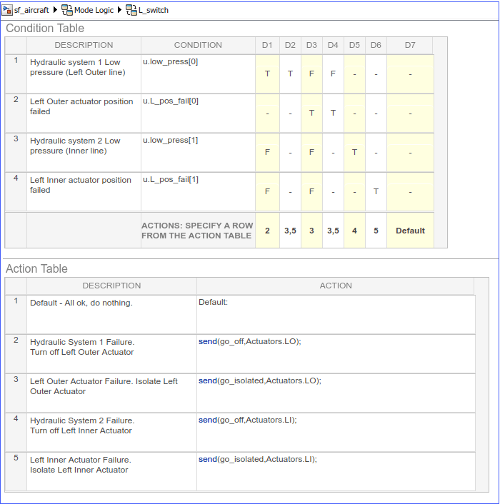
The first requirement indicates that if a failure is only detected in the hydraulic pressure 1 system, turn off the left outer actuator. In the truth table, this requirement is represented by the decision D1. If there is low pressure in the hydraulic system 1, then D1 specifies that action 2 is performed. Action 2 sends an event go_off to the left actuator, Actuators.LO.
Similarly, the other requirements are mapped to the appropriate actions in the truth table. For example, if the left outer actuator fails, D3 causes action 3. Action 3 sends the event go_isolated to Actuators.LO to isolate the left actuator.
The entry and during actions of the chart call the truth table functions so the fault checks execute at each time step.
Recover from Hydraulic Failures
The fault detection control logic enables the system to recover from a hydraulic circuit failure. For example, to bring the Hydraulic Circuit 1 back online, in the Failure Injection UI, clear the H1 check box and click Update. In the chart, the condition !u.low_press[0] becomes true, so the substate LO transitions from the Off mode to the Standby mode. As a result, the left outer actuator can then be activated in the event that the fault detection system registers another failure later in the simulation.
Isolate Actuators After Failures
When the fault detection system registers a failure in one of the actuators, that actuator can no longer be activated. In the chart Mode Logic, the failure of an actuator is represented by the substate Isolated. This substate has no outgoing transitions so once an actuator enters the Isolated state, it remains in that state for the rest of the simulation.
References
Pieter J. Mosterman and Jason Ghidella, "Model Reuse for the Training of Fault Scenarios in Aerospace," in Proceedings of the AIAA® Modeling and Simulation Technologies Conference, CD-ROM, paper 2004-4931, August 16 - 19, 2004, Rhode Island Convention Center, Providence, RI.
Jason R. Ghidella and Pieter J. Mosterman, "Applying Model-Based Design to a Fault Detection, Isolation, and Recovery System," in Military Embedded Systems, Summer, 2006.
Related Topics
You can also select a web site from the following list:
Americas
- América Latina (Español)
- Canada (English)
- United States (English)
Europe
- Belgium (English)
- Denmark (English)
- Deutschland (Deutsch)
- España (Español)
- Finland (English)
- France (Français)
- Ireland (English)
- Italia (Italiano)
- Luxembourg (English)
- Netherlands (English)
- Norway (English)
- Österreich (Deutsch)
- Portugal (English)
- Sweden (English)
- Switzerland
- United Kingdom (English)