Antenna Toolbox
Design, analyze, and visualize antenna elements and antenna arrays
Have questions? Contact Sales.
Have questions? Contact Sales.
Antenna Toolbox provides functions and apps for the design, analysis, and visualization of antenna elements and arrays. You can design standalone antennas and build arrays of antennas using predefined elements with parameterized geometry, arbitrary planar structures, or custom 3D structures described with STL files.
Antenna Toolbox uses electromagnetic solvers, including the method of moments (MoM), to compute impedance, current distribution, efficiency, and near-field and far-field radiation patterns. To improve the antenna design, you can use manual methods or use the optimization methods provided in the toolbox. Antenna geometry and analysis results can be visualized in 2D and 3D. The toolbox lets you integrate antenna array patterns into wireless systems for simulating beamforming and beam steering algorithms. The impedance analysis results can be used to design matching networks for integration with the RF front-end. You can install the antennas on large platforms such as vehicles or aircraft and analyze the effects of the structure on antenna performance. You can import STL and Gerber files to analyze a pre-existing structure or export them to share or manufacture your design. A site viewer enables you to visualize antenna coverage on a 3D terrain map using a variety of propagation models, including ray tracing.

Use Antenna Designer app to interactively design and visualize antennas using a catalog of nearly 100 parameterized elements, including various dipole, monopole, patch, spiral, fractal, and horn antennas. Add backing structures such as reflectors or cavities. Specify metal properties and dielectric substrates to estimate losses and efficiency.
Use Antenna Array Designer app to interactively design linear, rectangular, circular, and conformal arrays and compute the effect of mutual coupling. Perform infinite array analysis for modelling large antennas.

Analyze antenna elements and arrays using the full-wave 3D MoM. Compute port properties such as impedance and S-parameters, current and charge distribution, and near- and far-field radiation patterns. Compare analysis results with antenna measurements or with state-of-the-art scientific articles.
Use PCB Antenna Designer app to interactively design antennas and arrays. Import Gerber files or combine geometric shapes to define the boundary of the antenna, add multiple metal and dielectric layers, insert vias, and specify probe or insert feed points.

Use SADEA optimization (ML based) technique for multiple design variables to improve the performance of your antenna. Integrate with common optimization techniques available in Global Optimization Toolbox. Use the impedance and S-parameters of antennas and antenna arrays in the design of matching networks using RF Toolbox. Use RF PCB Toolbox to design distributed matching networks using the catalog elements.

Install antennas and antenna arrays on platforms such as cars, airplanes, or ships. Determine the radar cross section (RCS) of large objects for accurate target detection. Solve the large structures using Physical Optics (PO), MoM-PO, or Fast Multipole Method (FMM).

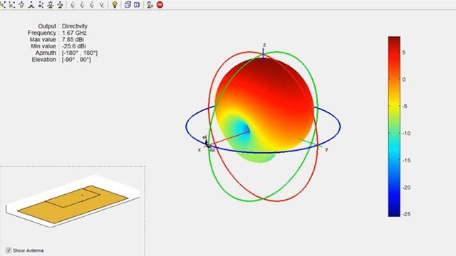
Import radiation patterns from MSI Planet antenna files (.MSI or .PLN). Visualize far- and near-field data using 3D or polar plots. Interactively inspect the data and compute antenna metrics. Reconstruct the 3D radiation pattern from 2D orthogonal slices.
Compute coverage and communication link properties using 3D geographical maps. Account for earth diffraction and reflection using Longley-Rice or Terrain Integrated Rough Earth Model™ (TIREM™) propagation models. Evaluate coverage in urban scenarios using ray tracing propagation models.
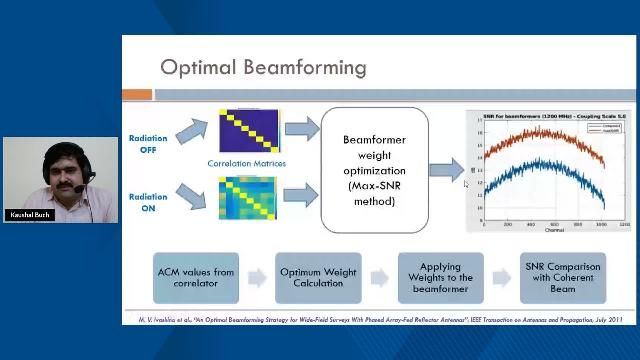
“Analysis of Vivaldi element pattern, forming an array and performing mutual coupling analysis for the receiver chain was key to system simulation in implementing an aperture level beamforming chain for Radio astronomy application”
Kaushal Buch, Giant Metrewave Radio Telescope (GMRT) NCRA-TIFR
30 days of exploration at your fingertips.
Get pricing information and explore related products.
Your school may already provide access to MATLAB, Simulink, and add-on products through a campus-wide license.
You can also select a web site from the following list
Americas
Europe
Asia Pacific