Developing AUTOSAR Adaptive Software for a Driver Monitoring System with Model-Based Design
By Thomas Kleinhenz, Seyed Nourbakhsh, and Stefan Zürbes, Elektrobit
More than 1 billion devices in over 100 million vehicles worldwide run embedded software developed by Elektrobit (EB). Much of this software was developed and verified using a standard V-model and the ASPICE process. While the devices work well, application software development was slowed by hand-coding and other labor-intensive manual tasks.
Our team set out to show that Model-Based Design could accelerate development of end-to-end, AUTOSAR Adaptive software systems. The project we chose was a prototype driver monitoring system that issues an alarm if the driver's eyes close and do not immediately reopen, indicating that the driver is falling asleep (Figure 1). To illustrate how efficiently we could develop the embedded software with Model-Based Design, we gave ourselves an ambitious deadline: design, implement, test, and verify the entire system in just three months. Using a traditional approach, the same project would have taken at least a year.
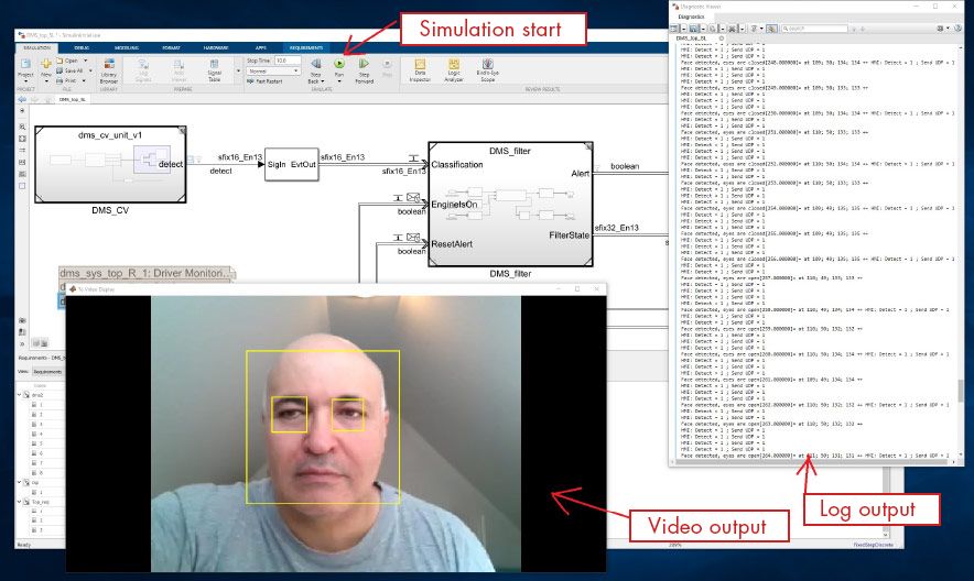
Figure 1. Simulation of the driver monitoring system showing face and eyes detected in the video stream.
Defining Requirements and Partitioning the Design
We began the project by defining requirements. High-level requirements included detecting closed eyes even when the driver is wearing glasses, keeping the false alarm rate below 3%, and sending alerts via Adaptive AUTOSAR to an EB human machine interface (HMI).
At this early stage, we worked with MathWorks engineers to develop the system architecture and map our requirements to functional blocks within the architecture (Figure 2). At the top level, our design has two main blocks. The first is a computer vision component that processes input from the camera and generates signals based on the video stream—for example, “face detected,” “eyes detected,” and “eyes closed.” The second is an AUTOSAR Adaptive function block that filters these signals and determines whether to trigger the alarm. This block includes an interface to the EB corbos AdaptiveCore software framework, which is used to integrate the block with the HMI.

Figure 2. Top-level Simulink model of the driver monitoring system.
Modeling and Verifying the Design
By partitioning the design into components with clearly defined interfaces (Figure 3), we were able to work on each component independently. We modeled the computer vision component in Simulink®, using a pretrained deep learning network and Computer Vision Toolbox™ to detect faces and eyes. To verify this model, we performed simulations in which the model processed prerecorded videos of drivers’ faces. The videos were recorded from various angles and in different ambient light conditions. It included drivers with and without eyeglasses to ensure that the system could detect closed eyes under a range of operating scenarios.
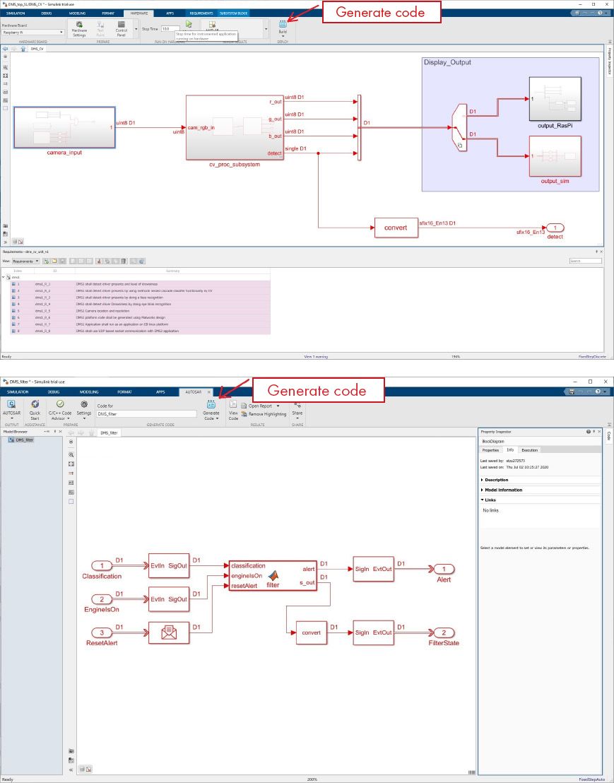
Figure 3. Simulink models of the computer vision component (top) and filtering component (bottom).
The filtering component takes the output of the computer vision component as input. It tracks the values of the “eyes detected” and “eyes closed” signals, filters out short blinks, and when these signals indicate that the driver’s eyes have been closed for too long, initiates the alarm via the AUTOSAR Adaptive communication to the EB AdaptiveCore software framework. We generated a unit test model from our top-level Simulink model so that we could perform system verification and design evaluation in accordance with ISO 26262.
Code Generation and Hardware Deployment
After verifying the design via simulation, we deployed and tested it on our prototype hardware setup. The setup consisted of two Raspberry Pi™ 3 B+ boards, one for the DMS system and another for the test setup, including the HMI, driver input, and environment. Both boards were linked via an Ethernet connection (Figure 4).

Figure 4. Hardware test setup.
We generated MISRA®-compliant C/C++ code for both the computer vision component and the filtering component. After compiling the computer vision component code, we deployed it directly to the first Raspberry Pi board. For the filtering component, we imported the generated code, including the ARXML files, into EB corbos Studio. We compiled the component in corbos Studio and deployed it as an AUTOSAR software component to the same Raspberry Pi. The computer vision and filtering components were linked via an interprocess communication (IPC) interface. A second Raspberry Pi board was used to run the EB corbos AdaptiveCore software base and EB GUIDE HMI to represent a vehicle instrument cluster.
With the code running on the two boards, we tested the system with a live camera video stream and verified that the HMI correctly issued the “eyes closed” alert when the individuals in the video closed their eyes.
From Proof-of-Concept to Real-World Applications
Since the driver management system was a proof-of-concept prototype, there was no need to strictly follow ISO guidelines during development. In preparation for projects that do require ISO compliance, however, we used Model Advisor to check our models for requirements coverage and for compliance with ISO 26262, ISO 61508, and MISRA C:2012 standards.
Having demonstrated the ability of Model-Based Design to accelerate Adaptive AUTOSAR software development at EB, we are now working to expand its use and demonstrating it to automotive tier-1 suppliers and OEMs. Our team plans to incorporate security features and processor-in-the-loop testing into the workflow, and we are helping colleagues in other EB locations get started with Model-Based Design.
Published 2021