5G NR PRACH Detection and False Alarm Test
This example implements the physical random access channel (PRACH) missed detection and false alarm conformance tests, as defined in TS 38.141-1. You can measure the probability of correct detection of the PRACH preamble in the presence of a preamble signal or switch the PRACH transmission off to measure the false alarm probability.
Introduction
The PRACH is an uplink transmission used by User Equipment (UE) to initiate synchronization with the gNodeB. TS 38.141-1 Section 8.4.1.5 defines the probability of PRACH detection to be greater than or equal to 99% at specific SNR values for a set of PRACH configurations and propagation conditions. There are several detection error cases:
Detecting an incorrect preamble
Not detecting a preamble
Detecting the correct preamble but with the wrong timing estimation
TS 38.141-1 states that a correct detection is achieved when the estimation error of the timing offset of the strongest path is less than the time error tolerance given in Table 8.4.1.1-1. For channel propagation conditions TDLC300-100 and PRACH preamble format 0, the time error tolerance is 2.55 microseconds.
In this example, a PRACH waveform is configured and passed through an appropriate channel. At the receiver side, the example performs PRACH detection and calculates the PRACH detection probability. The example considers the parameters defined in TS 38.141-1 Table 8.4.1.5-1 and Table A.6-1. These are: normal mode (i.e., unrestricted set), 2 receive antennas, TDLC300-100 channel, normal cyclic prefix, burst format 0, SNR -6.0 dB. If you change the PRACH configuration to use one of the other PRACH preamble formats listed in Table A.6-1, you need to update the values of the time error tolerance and the SNR, according to TS 38.141-1 Table 8.4.1.1-1 and Tables 8.4.1.5-1 to 8.4.1.5-3, respectively.
Simulation Configuration
The example considers 10 PRACH slots at a number of SNRs. You should use a large number of numPRACHSlots to produce meaningful results. You can set SNRdB as an array of values or a scalar. For an explanation of the SNR definition that this example uses, see SNR Definition Used in Link Simulations. Table 8.4.1.5-1 in TS 38.141-1 specifies the frequency offset foffset that is modeled between the transmitter and receiver. The timeErrorTolerance variable specifies the time error tolerance, as defined in Table 8.4.1.1-1 in TS 38.141-1. You can set the detection threshold to a value in the range [0,1] or to empty to use the default value in the nrPRACHDetect function. To simulate a false alarm test, disable the PRACH transmission by setting prachEnabled to false instead.
numPRACHSlots = 10;              % Number of PRACH slots to simulate at each SNR
SNRdB = [-21, -16, -11, -6, -1]; % SNR range in dB
foffset = 400.0;                 % Frequency offset in Hz
timeErrorTolerance = 2.55;       % Time error tolerance in microseconds
threshold = [];                  % Detection threshold
prachEnabled = true;             % Enable PRACH transmission. To simulate false alarm test, disable PRACH transmission.
Carrier Configuration
Use the nrCarrierConfig configuration object carrier to specify the carrier settings. The example considers a carrier characterized by a subcarrier spacing of 15 kHz and a bandwidth of 5 MHz. That is, the carrier spans 25 resource blocks, according to Table 5.3.2-1 in TS 38.104.
carrier = nrCarrierConfig;
carrier.SubcarrierSpacing = 15;
carrier.NSizeGrid = 25;

% Compute the OFDM-related information
ofdmInfo = nrOFDMInfo(carrier);
PRACH Configuration
Table A.6-1 in TS 38.141-1 specifies the PRACH configurations to use for the PRACH detection conformance test.
Set the PRACH configuration by using the nrPRACHConfig configuration object prach, according to Table A.6-1 and Section 8.4.1.4.2 in TS 38.141-1.
% Set PRACH configuration
prach = nrPRACHConfig;
prach.FrequencyRange = 'FR1';                    % Frequency range
prach.DuplexMode = 'FDD';                        % Frequency Division Duplexing (FDD)
prach.ConfigurationIndex = 27;                   % Configuration index for format 0
prach.SubcarrierSpacing = 1.25;                  % Subcarrier spacing
prach.SequenceIndex = 22;                        % Logical sequence index
prach.PreambleIndex = 32;                        % Preamble index
prach.RestrictedSet = 'UnrestrictedSet';         % Normal mode
prach.FrequencyStart = 0;                        % Frequency location

% Define the value of ZeroCorrelationZone using the NCS table stored in
% the nrPRACHConfig object
switch prach.Format
    case {'0','1','2'}
        ncsTable = nrPRACHConfig.Tables.NCSFormat012;
        ncsTableCol = (string(ncsTable.Properties.VariableNames) == prach.RestrictedSet);
    case '3'
        ncsTable = nrPRACHConfig.Tables.NCSFormat3;
        ncsTableCol = (string(ncsTable.Properties.VariableNames) == prach.RestrictedSet);
    otherwise
        ncsTable = nrPRACHConfig.Tables.NCSFormatABC;
        ncsTableCol = contains(string(ncsTable.Properties.VariableNames), num2str(prach.LRA));
end
NCS = 13;
zeroCorrelationZone = ncsTable.ZeroCorrelationZone(ncsTable{:,ncsTableCol}==NCS);
prach.ZeroCorrelationZone = zeroCorrelationZone; % Cyclic shift index
Propagation Channel Configuration
Use the nrTDLChannel object to configure the tapped delay line (TDL) propagation channel model channel as described in TS 38.141-1 Table 8.4.1.1-1.
channel = nrTDLChannel;
channel.DelayProfile = "TDLC300";           % Delay profile
channel.MaximumDopplerShift = 100.0;        % Maximum Doppler shift in Hz
channel.SampleRate = ofdmInfo.SampleRate;   % Input signal sample rate in Hz
channel.MIMOCorrelation = "Low";            % MIMO correlation
channel.TransmissionDirection = "Uplink";   % Uplink transmission
channel.NumReceiveAntennas = 2;             % Number of receive antennas
channel.NormalizePathGains = true;          % Normalize delay profile power
channel.Seed = 42;                          % Channel seed. Change this for different channel realizations
channel.NormalizeChannelOutputs = true;     % Normalize for receive antennas

% Get the channel characteristic information
channelInfo = info(channel);
Loop for SNR Values
Use a loop to run the simulation for the set of SNR points given by the vector SNRdB. The SNR vector configured here is a range of SNR points including a point at -6.0 dB, the SNR at which the test requirement for PRACH detection rate (99%) is to be achieved for preamble format 0, as discussed in Table 8.4.1.5-1 in TS 38.141-1.
hNRPRACHWaveformGenerator generates an output signal normalized to the same transmit power as for an uplink data transmission within the 5G Toolbox™. Therefore, the same normalization must take place on the noise added to the PRACH. The noise added before OFDM demodulation will be amplified by the IFFT by a factor equal to the square root of the size of the IFFT ( ). To ensure that the power of the noise added is normalized after demodulation, and thus to achieve the desired SNR, the desired noise power is divided by . In addition, as real and imaginary parts of the noise are created separately before being combined into complex additive white Gaussian noise, the noise amplitude is scaled by
  so the generated noise power is 1.
At each SNR test point, calculate the detection probability on a slot by slot basis using these steps:
PRACH Transmission: Use
hNRPRACHWaveformGeneratorto generate a PRACH waveform. Send the PRACH preambles with the timing offsets defined in TS 38.141-1 Figure 8.4.1.4.2-2. Set a timing offset base value to 50% of the number of cyclic shifts for PRACH generation. This offset is increased for each preamble, adding a step value of 0.1 microseconds, until the end of the tested range, which is 0.9 microseconds for PRACH preamble format 0. This pattern then repeats.Noisy Channel Modeling: Pass the waveform through a TDL channel and add additive white Gaussian noise. Add additional samples to the end of the waveform to cover the range of delays expected from the channel modeling (a combination of implementation delay and channel delay spread). This implementation delay is then removed to ensure the implementation delay is not interpreted as an actual timing offset in the preamble detector.
Application of Frequency Offset: Apply the frequency offset to the received waveform as defined by the specification.
PRACH Detection: Perform PRACH detection using the
nrPRACHDetectfunction for all cell preamble indices (0:63). Use the detected PRACH index and offset returned bynrPRACHDetectto determine where a detection was successful according to the constraints discussed in the Introduction section.
% Initialize variables storing detection probability at each SNR
pDetection = zeros(size(SNRdB));

% Store the configuration parameters needed to generate the PRACH waveform
waveconfig.NumSubframes = prach.SubframesPerPRACHSlot;
waveconfig.Windowing = [];
waveconfig.Carriers = carrier;
waveconfig.PRACH.Config = prach;
waveconfig.PRACH.Enable = prachEnabled;

% The temporary variables 'prach_init', 'waveconfig_init', 'ofdmInfo_init',
% and 'channelInfo_init' are used to create the temporary variables
% 'prach', 'waveconfig', 'ofdmInfo', and 'channelInfo' within the SNR loop
% to create independent instances in case of parallel simulation
prach_init = prach;
waveconfig_init = waveconfig;
ofdmInfo_init = ofdmInfo;
channelInfo_init = channelInfo;

for snrIdx = 1:numel(SNRdB) % comment out for parallel computing
% parfor snrIdx = 1:numel(SNRdB) % uncomment for parallel computing
% To reduce the total simulation time, you can execute this loop in
% parallel by using the Parallel Computing Toolbox. Comment out the 'for'
% statement and uncomment the 'parfor' statement. If the Parallel Computing
% Toolbox(TM) is not installed, 'parfor' defaults to normal 'for' statement

    % Display progress in the command window
    timeNow = char(datetime('now','Format','HH:mm:ss'));
    fprintf([timeNow ': Simulating SNR = %+5.1f dB...'], SNRdB(snrIdx));

    % Set the random number generator settings to default values
    rng('default');

    % Initialize variables for this SNR point, required for initialization
    % of variables when using the Parallel Computing Toolbox
    prach = prach_init;
    waveconfig = waveconfig_init;
    ofdmInfo = ofdmInfo_init;
    channelInfo = channelInfo_init;

    % Reset the channel so that each SNR point will experience the same
    % channel realization
    reset(channel);

    % Normalize noise power to account for the sampling rate, which is a
    % function of the IFFT size used in OFDM modulation. The SNR is defined
    % per carrier resource element for each receive antenna.
    SNR = 10^(SNRdB(snrIdx)/10);
    N0 = 1/sqrt(2.0*channel.NumReceiveAntennas*double(ofdmInfo.Nfft)*SNR);

    % Detected preamble count
    detectedCount = 0;

    % Loop for each PRACH slot
    numActivePRACHSlots = 0;
    for nSlot = 0:numPRACHSlots-1

        % Generate PRACH waveform for the current slot
        prach.NPRACHSlot = nSlot;
        waveconfig.PRACH.Config.NPRACHSlot = nSlot;
        [waveform,~,winfo] = hNRPRACHWaveformGenerator(waveconfig);

        % Set PRACH timing offset in microseconds as per TS 38.141-1 Figure
        % 8.4.1.4.2-2 and Figure 8.4.1.4.2-3
        if prach.LRA==839 % Long preamble, values as in Figure 8.4.1.4.2-2
            baseOffset = ((winfo.WaveformResources.PRACH.Resources.PRACHSymbolsInfo.NumCyclicShifts/2)/prach.LRA)/prach.SubcarrierSpacing*1e3; % (microseconds)
            timingOffset = baseOffset + mod(nSlot,10)/10; % (microseconds)
        else % Short preamble, values as in Figure 8.4.1.4.2-3
            baseOffset = 0; % (microseconds)
            timingOffset = baseOffset + mod(nSlot,9)/10; % (microseconds)
        end
        sampleDelay = fix(timingOffset / 1e6 * ofdmInfo.SampleRate);

        % Generate transmit waveform
        txwave = [zeros(sampleDelay,1); waveform];

        % Pass data through channel model. Append zeros at the end of the
        % transmitted waveform to flush channel content. These zeros take
        % into account any delay introduced in the channel. This is a mix
        % of multipath delay and implementation delay. This value may
        % change depending on the sampling rate, delay profile and delay
        % spread
        rxwave = channel([txwave; zeros(channelInfo.MaximumChannelDelay, size(txwave,2))]);

        % Add noise
        noise = N0*complex(randn(size(rxwave)), randn(size(rxwave)));
        rxwave = rxwave + noise;

        % Skip this slot if the PRACH is inactive.
        % Skip the detection of this slot after advancing the channel to
        % make sure that the channel is always synchronized with the
        % current slot.
        % If the PRACH is inactive in this slot, the receiver should not
        % expect any PRACH transmission and thus should not even try to
        % detect a PRACH. Skipping the detection of an inactive slot is
        % particularly important when performing a conformance test. If the
        % PRACH is inactive, the reference waveform computed internally in
        % the |nrPRACHDetect| function is empty. This leads to an empty
        % correlation and thus to an empty detected preamble. This empty
        % preamble leads to an incorrect value of the detection
        % probability.
        if isempty(winfo.WaveformResources.PRACH.Resources.PRACHSymbols)
            continue;
        end
        numActivePRACHSlots = numActivePRACHSlots + 1;

        % Remove the implementation delay of the channel filter
        rxwave = rxwave((channelInfo.ChannelFilterDelay + 1):end, :);

        % Apply frequency offset
        t = ((0:size(rxwave, 1)-1)/channel.SampleRate).';
        rxwave = rxwave .* repmat(exp(1i*2*pi*foffset*t), 1, size(rxwave, 2));

        % PRACH detection for all cell preamble indices
        [detected, offsets] = nrPRACHDetect(carrier, prach, rxwave, 'DetectionThreshold', threshold);

        % Test for preamble detection
        if (isscalar(detected))
            if ~prachEnabled
                % For the false alarm test, any preamble detected is wrong
                detectedCount = detectedCount + 1;
            else
                % Test for correct preamble detection
                if (detected==prach.PreambleIndex)

                    % Calculate timing estimation error
                    trueOffset = timingOffset/1e6; % (s)
                    measuredOffset = offsets(1)/channel.SampleRate;
                    timingerror = abs(measuredOffset-trueOffset);

                    % Test for acceptable timing error
                    if (timingerror<=timeErrorTolerance/1e6)
                        detectedCount = detectedCount + 1; % Detected preamble
                    end
                end
            end
        end

    end % of nSlot loop

    % Compute final detection probability for this SNR
    pDetection(snrIdx) = detectedCount/numActivePRACHSlots;

    % Display the detection probability for this SNR
    fprintf('Detection probability: %d%%\n', pDetection(snrIdx)*100);

end % of SNR loop
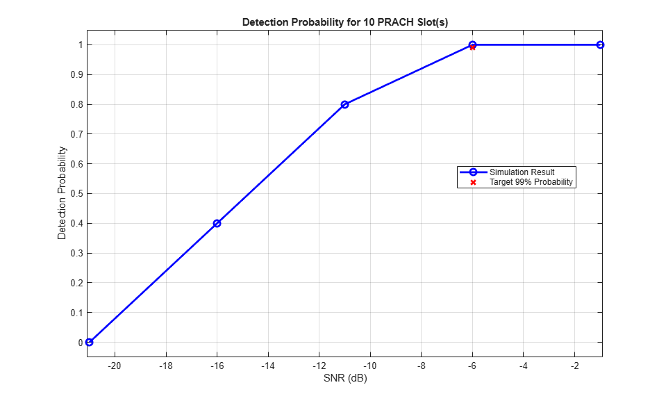
15:01:22: Simulating SNR = -21.0 dB...Detection probability: 0%
15:01:23: Simulating SNR = -16.0 dB...Detection probability: 40%
15:01:23: Simulating SNR = -11.0 dB...Detection probability: 80%
15:01:23: Simulating SNR =  -6.0 dB...Detection probability: 100%
15:01:23: Simulating SNR =  -1.0 dB...Detection probability: 100%
Results
At the end of the SNR loop, the example plots the calculated detection probabilities for each SNR value against the target probability.
% Sort the results in increasing values of SNR
[SNRdB_sorted,idx] = sort(SNRdB);
pDetection_sorted = pDetection(idx);

% Plot detection probability
figure('Name','Detection Probability');
plot(SNRdB_sorted,pDetection_sorted,'b-o','LineWidth',2,'MarkerSize',7);
title(['Detection Probability for ', num2str(numPRACHSlots) ' PRACH Slot(s)'] );
xlabel('SNR (dB)'); ylabel('Detection Probability');
grid on; hold on;
% Plot target probability
if prachEnabled
    % For a missed detection test, detection probability should be >= 99%
    pTarget = 99;
else
    % For a false alarm test, detection probability should be < 0.1%
    pTarget = 0.1; %#ok<UNRCH>
end
plot(-6.0,pTarget/100,'rx','LineWidth',2,'MarkerSize',7);
legend('Simulation Result', ['Target ' num2str(pTarget) '% Probability'],'Location','best');
minP = 0;
if(~isnan(min(pDetection_sorted)))
    minP = min([pDetection_sorted(:); pTarget]);
end
axis([SNRdB_sorted(1)-0.1 SNRdB_sorted(end)+0.1 minP-0.05 1.05])
References
3GPP TS 38.141-1. "NR; Base Station (BS) conformance testing. Part 1: Conducted conformance testing." 3rd Generation Partnership Project; Technical Specification Group Radio Access Network.
3GPP TS 38.104. "NR; Base Station (BS) radio transmission and reception." 3rd Generation Partnership Project; Technical Specification Group Radio Access Network.