Modeling and Analysis of Single Layer Multi-band U-Slot Patch Antenna
The standard rectangular microstrip patch is a narrowband antenna and provides 6-8 dBi Gain with linear polarization. This example based on the work done in [1],[2], models a broadband patch antenna using a slot in the radiator and develops a dual-band and a tri-band variation from it. In the process, the single wide response has been split into multiple narrow band regions catering to specific bands in the WiMAX standard. These patch antennas have been probe-fed.
Building the Single U-Slot Patch
Define parameters The basic U-slot patch antenna consists of a rectangular patch radiator within which a U-shaped slot has been cut out. As discussed in [1], the patch itself is on an air substrate and thick so as to enable higher bandwidths to be achieved. The presence of the slot structure achieves additional capacitance within the structure which combines with the inductance of the long probe feed to create a double resonance within the band. The geometry parameters based on [2] are defined and shown in a drawing below.
L = 26e-3;
W = 35.5e-3;
Uy1 = 19.5e-3;
Ux1 = 12e-3;
Ua1 = 2.1e-3;
Ud1 = 4.8e-3;
d = 13.5e-3;
h = 6e-3;

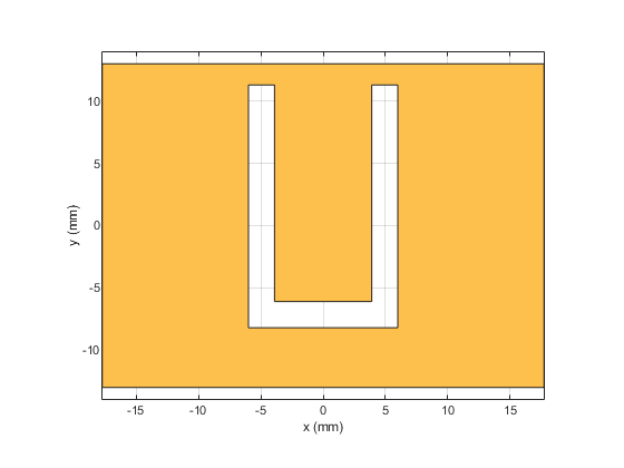
Define radiator shape - Single U-slot
Use the rectangle shape primitives in Antenna Toolbox™ to create the U-slot patch radiator shape. Boolean subtraction operation is used among the shape primitives for this purpose.
N1 = 2; %50;
N2 = 2; %10;
s = antenna.Rectangle('Length',W,'Width',L,'NumPoints',60);
h1 = antenna.Rectangle('Length',Ua1,'Width',Uy1,'NumPoints',[N2 N1 N2 N1],...
    'Center',[-Ux1/2 + Ua1/2, -L/2 + Ud1 + Uy1/2]);
h2 = antenna.Rectangle('Length',Ua1,'Width',Uy1,'NumPoints',[N2 N1 N2 N1],...
    'Center',[Ux1/2 - Ua1/2, -L/2 + Ud1 + Uy1/2]);
h3 = antenna.Rectangle('Length',Ux1,'Width',Ua1,'NumPoints' ,[N1 N2 N1 N2],...
    'Center',[0,-L/2 + Ud1 + Ua1/2]);
Uslot_patch = s-h1-h2-h3;
figure
show(Uslot_patch)
Define ground shape
Create the ground plane shape for the antenna. The groundplane in this case is rectangular and 71 mm x 52 mm in size.
Lgp = 71e-3;
Wgp = 52e-3;
p2  = antenna.Rectangle('Length',Lgp,'Width',Wgp,'NumPoints',10);
Define stack
Use the pcbStack to define the metal and dielectric layers and the feed for the single U-slot patch antenna. The layers are defined top-down. In this case, the top-most layer is a metal layer defined by the U-slot patch shape. The second layer is a dielectric material, air in this case, and the third layer is the metal ground plane.
d1 = dielectric('Air');
slotPatch = pcbStack;
slotPatch.Name = 'U-Slot Patch';
slotPatch.BoardThickness = h;
slotPatch.BoardShape = p2;
slotPatch.Layers = {Uslot_patch,d1,p2};
slotPatch.FeedLocations = [0 L/2-d 1 3];
slotPatch.FeedDiameter = 0.9e-3;
figure
show(slotPatch)

Calculate and Plot Reflection Coefficient
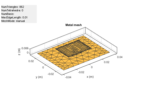
Mesh the structure by using a maximum edge length which is one-tenth the wavelength at the highest frequency of operation which is 6 GHz for this example. Compute and plot the reflection coefficient for this antenna over the band. The reflection coefficient is plotted with a reference impedance of 50 ohms.
figure
mesh(slotPatch,'MaxEdgeLength',.01,'MinEdgeLength',.001,'GrowthRate',0.7)
freq = linspace(3e9,6e9,200);
s1 = sparameters(slotPatch,freq);
s11Fig = figure;
rfplot(s1,1,1)
s11Ax = gca(s11Fig);
hold(s11Ax,'on');

Calculate and plot pattern
Plot the radiation pattern for this antenna at the frequencies of best match in the band.
figure
pattern(slotPatch,3.9e9)

figure
pattern(slotPatch,4.74e9)

Dual-band U-Slot Patch Antenna
Define Parameters
To achieve dual-band behavior as shown in [1], [2], the double resonance is modified such that the two contributing resonances, i.e. from the patch and from the slot do not merge. To do so the existing slot parameters are adjusted and a second slot is introduced into the structure. The parameters for the double U-slot are listed below as per [2] and a figure annotated with the variables used is shown.
Ux1 = 13e-3;
Ux2 = 22e-3;
Uy1 = 18.5e-3;
Uy2 = 7e-3;
Ua2 = 1e-3;
Ud1 = 5.8e-3;
Ud2 = 1.5e-3;

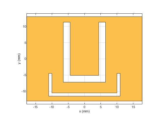
Create Double U-slot radiator
As before use the shape primitives, to create the geometry by using Boolean operations.
h1 = antenna.Rectangle('Length',Ua1,'Width',Uy1,'NumPoints',[N2 N1 N2 N1],'Center',[-Ux1/2 + Ua1/2, -L/2 + Ud1 + Uy1/2]);
h2 = antenna.Rectangle('Length',Ua1,'Width',Uy1,'NumPoints',[N2 N1 N2 N1],'Center',[Ux1/2 - Ua1/2, -L/2 + Ud1 + Uy1/2]);
h3 = antenna.Rectangle('Length',Ux1,'Width',Ua1,'NumPoints',[N1 N2 N1 N2],'Center',[0,-L/2 + Ud1 + Ua1/2]);
Uslot_patch = s-h1-h2-h3;
h4 = antenna.Rectangle('Length',Ua2,'Width',Uy2,'NumPoints',[N2 N1 N2 N1],'Center',[-Ux2/2 + Ua2/2, -L/2 + Ud2 + Uy2/2]);
h5 = antenna.Rectangle('Length',Ua2,'Width',Uy2,'NumPoints',[N2 N1 N2 N1],'Center',[Ux2/2 - Ua2/2, -L/2 + Ud2 + Uy2/2]);
h6 = antenna.Rectangle('Length',Ux2,'Width',Ua2,'NumPoints',[N1 N2 N1 N2],'Center',[0,-L/2 + Ud2 + Ua2/2]);
DoubleUslot_patch = Uslot_patch-h4-h5-h6;
figure
show(DoubleUslot_patch)
Modify Layers in Stack
Modify the existing stack by introducing the new radiator in the Layers property.
slotPatch.Layers = {DoubleUslot_patch,d1,p2};
figure
show(slotPatch)

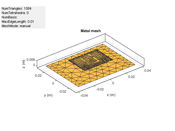
Mesh and Plot Reflection Coefficient
Mesh the structure at the highest frequency of operation and calculate the reflection coefficient.
figure
mesh(slotPatch,'MaxEdgeLength',.01,'MinEdgeLength',.001,'GrowthRate',0.5)
s2 = sparameters(slotPatch,freq);
figure(s11Fig);
rfplot(s2,1,1);

Triple-Band U-slot Patch Antenna Parameters
For triple-band operation a third U-slot is introduced and the existing slot parameters are adjusted. The parameters are shown below based on [2].
d   = 14.5e-3;
Ux1 = 14e-3;
Ux2 = 18e-3;
Ux3 = 22e-3;
Uy1 = 18.7e-3;
Uy2 = 9e-3;
Uy3 = 4e-3;
Ud2 = 3.5e-3;
Ud3 = 1.5e-3;
Ua1 = 2e-3;
Ua3 = 1e-3;

Create Triple U-slot radiator
N1 = 20; %50;
N2 = 10; %10;
h1 = antenna.Rectangle('Length',Ua1,'Width',Uy1,'NumPoints',[N2 N1 N2 N1],'Center',[-Ux1/2 + Ua1/2, -L/2 + Ud1 + Uy1/2]);
h2 = antenna.Rectangle('Length',Ua1,'Width',Uy1,'NumPoints',[N2 N1 N2 N1],'Center',[Ux1/2 - Ua1/2, -L/2 + Ud1 + Uy1/2]);
h3 = antenna.Rectangle('Length',Ux1,'Width',Ua1,'NumPoints',[N1 N2 N1 N2],'Center',[0,-L/2 + Ud1 + Ua1/2]);
Uslot_patch = s-h1-h2-h3;
h4 = antenna.Rectangle('Length',Ua2,'Width',Uy2,'NumPoints',[N2 N1 N2 N1],'Center',[-Ux2/2 + Ua2/2, -L/2 + Ud2 + Uy2/2]);
h5 = antenna.Rectangle('Length',Ua2,'Width',Uy2,'NumPoints',[N2 N1 N2 N1],'Center',[Ux2/2 - Ua2/2, -L/2 + Ud2 + Uy2/2]);
h6 = antenna.Rectangle('Length',Ux2,'Width',Ua2,'NumPoints',[N1 N2 N1 N2],'Center',[0,-L/2 + Ud2 + Ua2/2]);
DoubleUslot_patch = Uslot_patch-h4-h5-h6;
h7 = antenna.Rectangle('Length',Ua3,'Width',Uy3,'NumPoints',[N2 N1 N2 N1],'Center',[-Ux3/2 + Ua3/2, -L/2 + Ud3 + Uy3/2]);
h8 = antenna.Rectangle('Length',Ua3,'Width',Uy3,'NumPoints',[N2 N1 N2 N1],'Center',[Ux3/2 - Ua3/2, -L/2 + Ud3 + Uy3/2]);
h9 = antenna.Rectangle('Length',Ux3,'Width',Ua3,'NumPoints',[N1 N2 N1 N2],'Center',[0,-L/2 + Ud3 + Ua3/2]);
TripleUslot_patch = DoubleUslot_patch-h7-h8-h9;
figure
show(TripleUslot_patch)

Modify Layers in Stack
slotPatch.Layers = {TripleUslot_patch,d1,p2};
slotPatch.FeedLocations = [0 L/2-d 1 3];
figure
show(slotPatch)

Mesh and Plot Reflection Coefficient
figure
mesh(slotPatch,'MaxEdgeLength',.005,'MinEdgeLength',.001,'GrowthRate',0.7)

s3 = sparameters(slotPatch,freq);
figure(s11Fig)
rfplot(s3,1,1)
legend('Single','Double','Triple')
title('S_1_1')
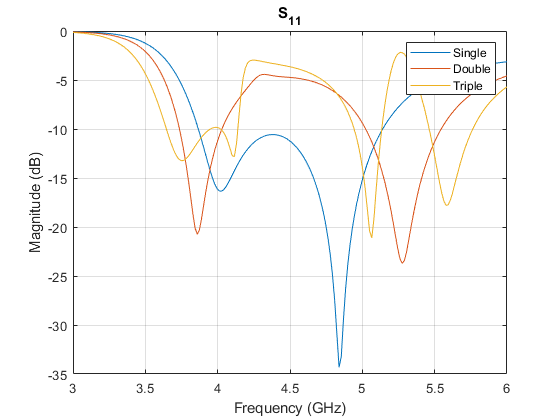
Conclusion
The models of the multi-band single layer U-slot patch antenna as discussed in [1], and [2] have been built and analyzed and agree well with results reported.
Reference
[1] K. F. Lee, S. L. S. Yang and A. Kishk, "The versatile U-slot patch antenna," 2009 3rd European Conference on Antennas and Propagation, Berlin, 2009, pp. 3312-3314.
[2] W. C. Mok, S. H. Wong, K. M. Luk and K. F. Lee, "Single-Layer Single-Patch Dual-Band and Triple-Band Patch Antennas," in IEEE Transactions on Antennas and Propagation, vol. 61, no. 8, pp. 4341-4344, Aug. 2013.
See Also
Select a Web Site
Choose a web site to get translated content where available and see local events and offers. Based on your location, we recommend that you select: United States.
You can also select a web site from the following list
Americas
- América Latina (Español)
- Canada (English)
- United States (English)
Europe
- Belgium (English)
- Denmark (English)
- Deutschland (Deutsch)
- España (Español)
- Finland (English)
- France (Français)
- Ireland (English)
- Italia (Italiano)
- Luxembourg (English)
- Netherlands (English)
- Norway (English)
- Österreich (Deutsch)
- Portugal (English)
- Sweden (English)
- Switzerland
- United Kingdom (English)
Asia Pacific
- Australia (English)
- India (English)
- New Zealand (English)
- 中国
- 日本Japanese (日本語)
- 한국Korean (한국어)