Find Channel Impulse Response
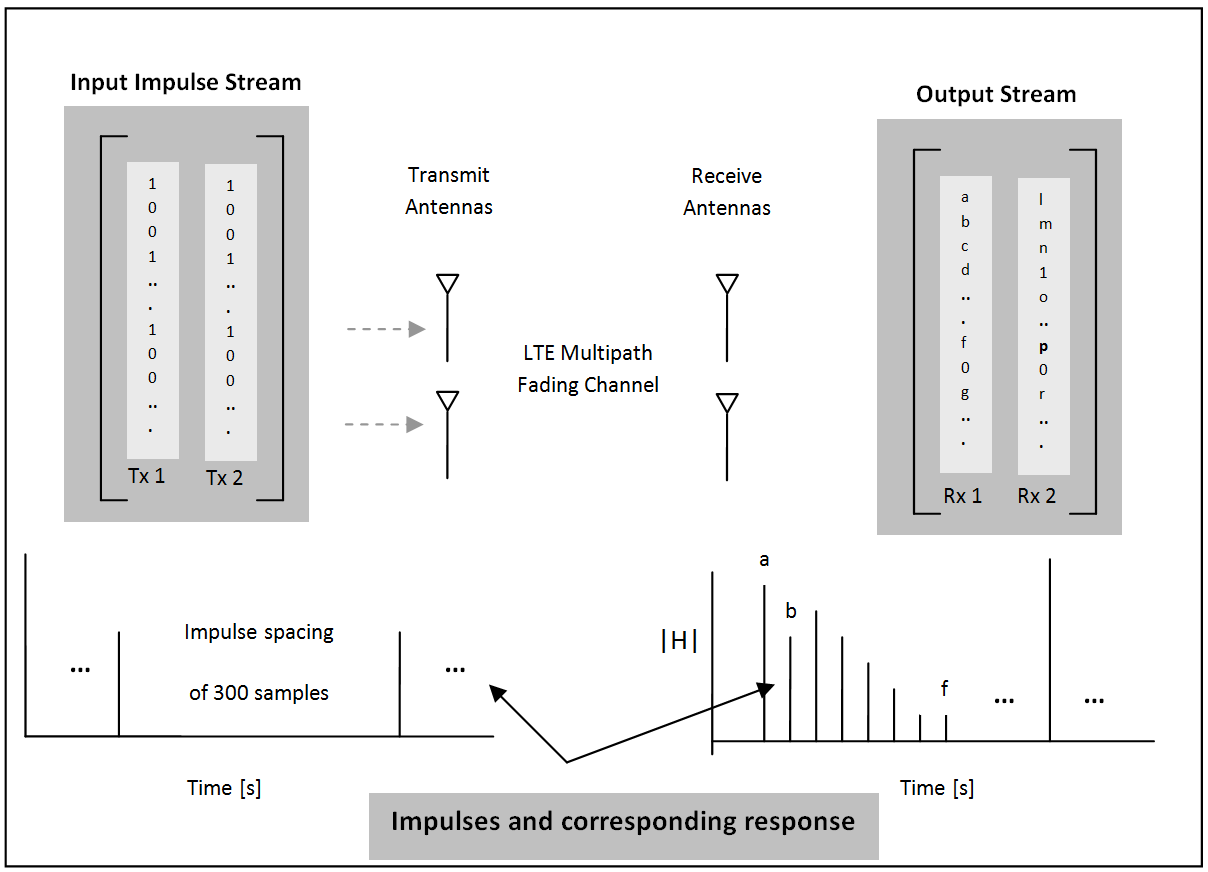
This example shows how to find the channel impulse response of a 2-by-2 MIMO system. The input is a matrix of impulses where each impulse is separated by 300 samples. Each column in the matrix, the size of which is the number of transmit antennas, is the input waveform to the channel model function and is therefore a series of impulses. This series of impulses allows the changing impulse response of the channel to be viewed over time. For clear visualization, the impulse spacing should be greater than maximum delay spread of the channel. The input waveform is passed through the LTE multipath fading channel model. The output matrix has complex samples corresponding to each receive antenna.
Pre-configure the LTE multipath fading channel. To do so, set up a simple structure and specify the fading channel parameters.
channel.Seed = 1;
channel.NRxAnts = 2;
channel.DelayProfile = 'EVA';
channel.DopplerFreq = 300;
channel.CarrierFreq = 2e9;
channel.MIMOCorrelation = 'Low';
channel.SamplingRate = 1/10e-9;
channel.InitTime = 0;
channel.InitPhase = 'Random';
channel.ModelType = 'GMEDS';
channel.NTerms = 16;
channel.NormalizeTxAnts = 'On';
channel.NormalizePathGains = 'On';
Create two identical input streams of data. These input streams are passed through two transmit antennas, as shown in the preceding figure.
nAntIn = 2;
impulseSpacing = 300;
noImpResponse = 150;
nInputSamples = impulseSpacing * noImpResponse;
in = zeros(nInputSamples, nAntIn);
onesLocations = 1:impulseSpacing:nInputSamples;
in(onesLocations,1) = 1;
The variable nAntIn is the number of transmit antennas. The variable impulseSpacing is greater than the maximum channel delay spread. The variable noImpResponse is the number of impulse responses to calculate.
Filter with the LTE fading channel. To do so, call the lteFadingChannel function. This function generates an LTE multi-path fading channel, as specified in TS 36.101 [1]. The first input argument, in, is an array of LTE transmitted samples. Each row contains the waveform samples for each of the transmit antennas. These waveforms are filtered with the delay profiles as specified in the parameter structure, channel.
out = lteFadingChannel(channel,in);
Finally, plot the receive waveform, showing the channel impulse response for both receive antennas.
for antNo = 1:channel.NRxAnts
    figure
    mesh(squeeze(abs(reshape(out(:,antNo), ...
        impulseSpacing,noImpResponse).')))
    titleStr = ['Rx Antenna' num2str(antNo)];
    title({'Channel Impulse Response for LTE fading channel',titleStr})
    ylabel('number of impulses')
    xlabel('Impulse spacing [no of samples]')
    zlabel('|H|')
end
![Figure contains an axes object. The axes object with title Channel Impulse Response for LTE fading channel Rx Antenna1, xlabel Impulse spacing [no of samples], ylabel number of impulses contains an object of type surface.](../../examples/lte/win64/FindChannelImpulseResponseExample_02.png)
![Figure contains an axes object. The axes object with title Channel Impulse Response for LTE fading channel Rx Antenna2, xlabel Impulse spacing [no of samples], ylabel number of impulses contains an object of type surface.](../../examples/lte/win64/FindChannelImpulseResponseExample_03.png)
References
3GPP TS 36.101 "User Equipment (UE) radio transmission and reception".
See Also
lteFadingChannel | lteHSTChannel | lteMovingChannel