NB-IoT NPUSCH Block Error Rate Simulation
This example shows how to create an NB-IoT Narrowband Physical Uplink Shared Channel (NPUSCH) Block Error Rate (BLER) simulation in frequency-selective fading and Additive White Gaussian Noise (AWGN) using LTE Toolbox™.
Introduction
3GPP introduced a new air interface, Narrowband IoT (NB-IoT), optimized for low data rate machine-type communications in LTE-Advanced Pro Release 13. NB-IoT provides cost and power efficiency improvements as it avoids the need for complex signaling overhead required for LTE-based systems.
The example generates an NB-IoT NPUSCH BLER curve for a number of SNR points and transmission parameters. NPUSCH and narrowband demodulation reference signal (DRS) are transmitted in all slots. Operating on a slot-by-slot basis for each SNR point, the BLER calculation comprises these steps:
Generate a resource grid and populate it with NPUSCH symbols
Create the baseband waveform by SC-FDMA modulating the grid
Pass the waveform through a noisy fading channel
Perform receiver operations (SC-FDMA demodulation, channel estimation, and equalization)
Obtain the block CRC by decoding the equalized symbols
Determine the performance of the NPUSCH by using the block CRC result at the output of the channel decoder
Simulation Configuration
The simulation length is 5 UL-SCH transport blocks for a number of SNR points SNRdB for different repetitions simReps. To produce meaningful throughput results, you should use a larger number of transport blocks (numTrBlks). SNRdB and simReps can be a specified as a scalar or a numeric array.
numTrBlks = 5;              % Number of simulated transport blocks
SNRdB = [-20 -18 -15 -12.5 -10 -6.4 -3.5 0.7];  % Range of SNR values in dB
simReps = [2 16 64];        % Repetitions to simulate
NPUSCH Configuration
In this section we configure the parameters required for NPUSCH generation. There are two types of payload defined for NPUSCH transmission, format 1 ('Data') and format 2 ('Control'). For format 1, the UE uses the combination of modulation and coding scheme (MCS) and resource assignment signaled via the DCI to determine the transport block size from the set defined in TS 36.213 Table 16.5.1.2-2. For format 2, the NPUSCH carries the 1 bit ACK/NACK. The chs.NPUSCHFormat parameter specifies the format and infoLen specifies the transport block length. The parameters used in this example are as per the A16-5 FRC defined in TS 36.104 Annex A.16.
HARQ Operation NB-IoT has one or two UL HARQ processes and HARQ operation is asynchronous for NB-IoT UEs except for the repetitions within a bundle. Bundling operation relies on the HARQ entity for invoking the same HARQ process for each transmission that is part of the same bundle. Within a bundle, HARQ retransmissions are non-adaptive. They are triggered without waiting for feedback from the reception of previous repetitions. An uplink grant corresponding to a new transmission or a retransmission of the bundle is only received after the last repetition of the bundle. A retransmission of a bundle is also a bundle. For more details, see TS 36.321 section 5.4.2. In this example the bundle retransmissions are not modeled.
ue = struct();                        % Initialize the UE structure
ue.NBULSubcarrierSpacing = '15kHz';   % 3.75kHz, 15kHz
ue.NNCellID = 10;                     % Narrowband cell identity

chs = struct();
chs.NPUSCHFormat = 'Data';        % NPUSCH payload type ('Data' or 'Control')
% The number of subcarriers used for NPUSCH 'NscRU' depends on the NPUSCH
% format and subcarrier spacing 'NBULSubcarrierSpacing' as shown in TS 36.211
% Table 10.1.2.3-1. There are 1,3,6 or 12 continuous subcarriers for NPUSCH
chs.NBULSubcarrierSet = 0:11;     % Range is 0-11 (15kHz); 0-47 (3.75kHz)
chs.NRUsc = length(chs.NBULSubcarrierSet);
% The symbol modulation depends on the NPUSCH format and NscRU as given by
% TS 36.211 Table 10.1.3.2-1
chs.Modulation = 'QPSK';
chs.CyclicShift = 0;        % Cyclic shift required when NRUsc = 3 or 6
chs.RNTI = 20;              % RNTI value
chs.NLayers = 1;            % Number of layers
chs.NRU = 1;                % Number of resource units
chs.SlotIdx = 0;            % The slot index
chs.NTurboDecIts = 5;       % Number of turbo decoder iterations
chs.CSI = 'On';             % Use channel CSI in PUSCH decoding

% RV offset signaled via DCI (See 36.213 16.5.1.2)
rvDCI = 0;
% Calculate the RVSeq used according to the RV offset
rvSeq = [2*mod(rvDCI+0,2)  2*mod(rvDCI+1,2)];

if strcmpi(chs.NPUSCHFormat,'Data')
    infoLen = 136;   % Transport block size for NPUSCH format 1
elseif strcmpi(chs.NPUSCHFormat,'Control')
    infoLen = 1;    % ACK/NACK bit for NPUSCH format 2
end
Propagation Channel Model Configuration
The structure channel contains the channel model configuration parameters.
channel = struct;                    % Initialize channel config structure
channel.Seed = 6;                    % Channel seed
channel.NRxAnts = 2;                 % 2 receive antennas
channel.DelayProfile ='ETU';         % Delay profile
channel.DopplerFreq = 1;             % Doppler frequency in Hz
channel.MIMOCorrelation = 'Low';     % Multi-antenna correlation
channel.NTerms = 16;                 % Oscillators used in fading model
channel.ModelType = 'GMEDS';         % Rayleigh fading model type
channel.InitPhase = 'Random';        % Random initial phases
channel.NormalizePathGains = 'On';   % Normalize delay profile power
channel.NormalizeTxAnts = 'On';      % Normalize for transmit antennas
Channel Estimator Configuration
In this example, the parameter perfectChannelEstimator controls channel estimator behavior. Valid values are true or false. When set to true, a perfect channel estimator is used. Otherwise a practical estimator is used, based on the values of the received NPUSCH DRS.
% Channel estimator behavior
perfectChannelEstimator = true;
The structure cec configures the practical channel estimator. An ETU delay profile with 1Hz Doppler causes the channel to change slowly over time. To ensure averaging over all subcarriers for the resource block, set the frequency window to 23 Resource Elements (REs). The variable channelEstimationLength configures the number of slots over which channel estimates are averaged, see TS 36.104 Table A.16.1-1 for suggested values for different NPUSCH configurations.
% Configure channel estimator
cec.PilotAverage = 'UserDefined';   % Type of pilot symbol averaging
cec.TimeWindow = 1;                 % Time window size in REs
cec.FreqWindow = 23;                % Frequency window size in REs
cec.InterpType = 'Cubic';           % 2D interpolation type
channelEstimationLength = 1;        % Channel estimation length in ms
For DRS signals in NPUSCH format 1, sequence-group hopping can be enabled or disabled by the higher layer cell-specific parameter groupHoppingEnabled. Sequence-group hopping for a particular UE can be disabled through the higher layer parameter groupHoppingDisabled as described in TS 36.211 Section 10.1.4.1.3. In this example, we use the SeqGroupHopping parameter to enable or disable sequence-group hopping
chs.SeqGroupHopping = 'on'; % Enable/Disable Sequence-Group Hopping for UE
chs.SeqGroup = 0;           % Higher-layer parameter groupAssignmentNPUSCH

% Get number of time slots in a resource unit NULSlots according to
% TS 36.211 Table 10.1.2.3-1
if strcmpi(chs.NPUSCHFormat,'Data')
    if chs.NRUsc == 1
        NULSlots = 16;
    elseif any(chs.NRUsc == [3 6 12])
        NULSlots = 24/chs.NRUsc;
    else
        error('Invalid number of subcarriers. NRUsc must be one of 1,3,6,12');
    end
elseif strcmpi(chs.NPUSCHFormat,'Control')
    NULSlots = 4;
else
    error('Invalid NPUSCH Format (%s). NPUSCHFormat must be ''Data'' or ''Control''',chs.NPUSCHFormat);
end
chs.NULSlots = NULSlots;
Block Error Rate Simulation Loop
To perform NB-IoT NPUSCH link level simulation and plot BLER results for a number of repetition levels, this example performs the following steps:
For NPUSCH format 1 transmission for UL data transfer:
Generate a random stream of bits with the size of the desired transport block
Perform CRC encoding, turbo encoding and rate matching to create the NPUSCH bits
Interleave the bits per resource unit to apply a time-first mapping and create the NPUSCH codeword
For NPUSCH format 2 used for signaling HARQ feedback for NPDSCH:
Perform bit repetition of the HARQ indicator to create the NPUSCH codeword
Then for either NPUSCH format:
Perform scrambling, modulation, layer mapping and precoding on the codeword to form the complex NPUSCH symbols
Map the NPUSCH symbols and the corresponding DRS to the resource grid
Generate the time domain waveform by performing SC-FDMA modulation of the resource grid
Pass the waveform through a fading channel with AWGN
Recover the transmitted grid by performing synchronization, channel estimation and MMSE equalization
Extract the NPUSCH symbols
Recover the transport block by demodulating the symbols and channel decoding the resulting bit estimates
Note that if practical channel estimation is configured (perfectChannelEstimator = false), practical timing estimation based on NPUSCH DRS correlation will also be performed. The timing offset is initialized to zero, intended to represent the initial synchronization after NPRACH reception. The timing estimate is then updated whenever the peak of the NPUSCH DRS correlation is sufficiently strong.
After de-scrambling, the repetitive slots are soft-combined before rate recovery. The transport block error rate is calculated for each SNR point. The evaluation of the block error rate is based on the assumption that all the slots in a bundle are used to decode the transport block at the UE. A bundle is defined in the MAC layer (see 3GPP TS 36.321 5.4.2.1) as the NPUSCH.NRU 
NPUSCH.NULSlots NPUSCH.NRep slots used to carry a transport block.
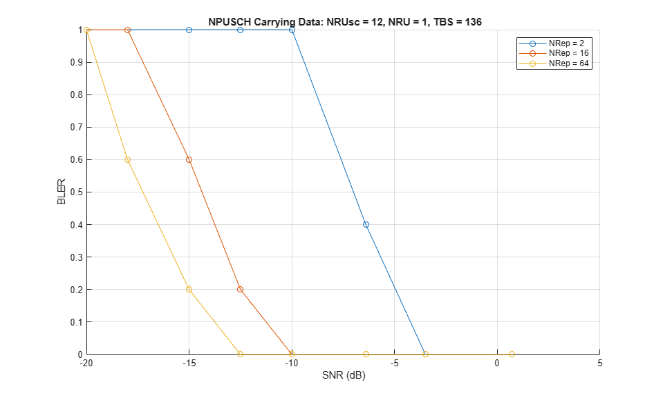
% Get the slot grid and number of slots per frame
emptySlotGrid = lteNBResourceGrid(ue); % Initialize empty slot grid
slotGridSize = size(emptySlotGrid);
NSlotsPerFrame = 20/(slotGridSize(1)/12);

tSlot = 10e-3/NSlotsPerFrame; % Slot duration
symbolsPerSlot = slotGridSize(2); % Number of symbols per slot

% Get a copy of the configuration variables ue, chs and channel to create
% independent simulation parfor loops
ueInit = ue;
chsInit = chs;
channelInit = channel;

for repIdx = 1:numel(simReps)

    chsInit.NRep = simReps(repIdx); % Number of repetitions of the NPUSCH
    NSlotsPerBundle = chsInit.NRU*chsInit.NULSlots*chsInit.NRep; % Number of slots in a codeword bundle
    TotNSlots = numTrBlks*NSlotsPerBundle;   % Total number of simulated slots

    % Initialize BLER and throughput result
    maxThroughput = zeros(length(SNRdB),1);
    simThroughput = zeros(length(SNRdB),1);
    bler = zeros(1,numel(SNRdB)); % Initialize BLER result

    for snrIdx = 1:numel(SNRdB)
    % parfor snrIdx = 1:numel(SNRdB)
    % To enable the use of parallel computing for increased speed comment out
    % the 'for' statement above and uncomment the 'parfor' statement below.
    % This needs the Parallel Computing Toolbox (TM). If this is not installed
    % 'parfor' will default to the normal 'for' statement.

        % Set the random number generator seed depending on the loop variable
        % to ensure independent random streams
        rng(snrIdx,'combRecursive');

        ue = ueInit;    % Initialize ue configuration
        chs = chsInit;  % Initialize chs configuration
        channel = channelInit; % Initialize fading channel configuration
        numBlkErrors = 0;  % Number of transport blocks with errors
        estate = struct('SlotIdx',chs.SlotIdx);  % Initialize NPUSCH encoder state
        dstate = estate;   % Initialize NPUSCH decoder state
        offset = 0;        % Initialize overall frame timing offset
        trblk = [];        % Initialize the transport block
        npuschHest = [];   % Initialize channel estimate
        noiseEst = [];     % Initialize noise estimate

        % Display the number of slots being generated
        fprintf('\nGenerating %d slots corresponding to %d transport block(s) at %gdB SNR\n',TotNSlots,numTrBlks,SNRdB(snrIdx));

        for slotIdx = 0+(0:TotNSlots-1)
            % Calculate the frame number and slot number within the frame
            ue.NFrame = fix(slotIdx/NSlotsPerFrame);
            ue.NSlot = mod(slotIdx,NSlotsPerFrame);
            % Create the slot grid
            slotGrid = emptySlotGrid;

            if isempty(trblk)

               % Initialize transport channel decoder state
               dstateULSCH = [];

               if strcmpi(chs.NPUSCHFormat,'Data')
                   % UL-SCH encoding is performed for the two RV values used for
                   % transmitting the codewords. The RV sequence used is determined
                   % from the rvDCI value signaled in the DCI and alternates
                   % between 0 and 2 as given in TS 36.213 Section 16.5.1.2

                   % Define the transport block which will be encoded to create the
                   % codewords for different RV
                   trblk = randi([0 1],infoLen,1);

                   % Determine the coded transport block size
                   [~, info] = lteNPUSCHIndices(ue,chs);
                   outblklen = info.G;
                   % Create the codewords corresponding to the two RV values used
                   % in the first and second block, this will be repeated till all
                   % blocks are transmitted
                   chs.RV = rvSeq(1); % RV for the first block
                   cw = lteNULSCH(chs,outblklen,trblk); % CRC and Turbo coding is repeated
                   chs.RV = rvSeq(2); % RV for the second block
                   cw = [cw lteNULSCH(chs,outblklen,trblk)]; %#ok<AGROW> % CRC and Turbo coding is repeated
               else
                   trblk = randi([0 1],1); % 1 bit ACK
                   % For ACK, the same codeword is transmitted every block as
                   % defined in TS 36.212 Section 6.3.3
                   cw = lteNULSCH(trblk);
               end
               blockIdx = 0; % First block to be transmitted
            end

            % Copy SlotIdx for the SCFDMA modulator
            chs.SlotIdx = estate.SlotIdx;

            % Set the RV used for the current transport block
            chs.RV = rvSeq(mod(blockIdx,size(rvSeq,2))+1);

            % NPUSCH encoding and mapping onto the slot grid
            txsym = lteNPUSCH(ue,chs,cw(:,mod(blockIdx,size(cw,2))+1),estate);
            slotGrid(lteNPUSCHIndices(ue,chs)) = txsym;

            % NPUSCH DRS and mapping on to the slot grid
            [dmrs,estate] = lteNPUSCHDRS(ue,chs,estate);
            slotGrid(lteNPUSCHDRSIndices(ue,chs)) = dmrs;

            % If a full block is transmitted, increment the clock counter so that
            % the correct codeword can be selected
            if estate.EndOfBlk
                blockIdx = blockIdx + 1;
            end

            % Perform SC-FDMA modulation to create the time domain waveform
            [txWaveform,scfdmaInfo] = lteSCFDMAModulate(ue,chs,slotGrid);

            % Add 25 sample padding. This is to cover the range of delays
            % expected from channel modeling (a combination of
            % implementation delay and channel delay spread)
            txWaveform =  [txWaveform; zeros(25, size(txWaveform,2))]; %#ok<AGROW>

            % Initialize channel time for each slot
            channel.InitTime = slotIdx*tSlot;

            % Pass data through channel model
            channel.SamplingRate = scfdmaInfo.SamplingRate;
            [rxWaveform,fadingInfo] = lteFadingChannel(channel, txWaveform);

            % Calculate noise gain
            SNR = 10^(SNRdB(snrIdx)/10);

            % Normalize noise power to take account of sampling rate, which is
            % a function of the IFFT size used in SC-FDMA modulation
            N0 = 1/sqrt(2.0*double(scfdmaInfo.Nfft)*SNR);

            % Create additive white Gaussian noise
            noise = N0*complex(randn(size(rxWaveform)), ...
                                randn(size(rxWaveform)));

            % Add AWGN to the received time domain waveform
            rxWaveform = rxWaveform + noise;

            %------------------------------------------------------------------
            %            Receiver
            %------------------------------------------------------------------

            % Perform timing synchronization, extract the appropriate
            % subframe of the received waveform, and perform SC-FDMA
            % demodulation
            if (perfectChannelEstimator)
                offset = hPerfectTimingEstimate(fadingInfo);
            else
                [t,mag] = lteULFrameOffsetNPUSCH(ue, chs, rxWaveform, dstate);
                % The function hSkipWeakTimingOffset is used to update the
                % receiver timing offset. If the correlation peak in 'mag'
                % is weak, the current timing estimate 't' is ignored and
                % the previous estimate 'offset' is used
                offset = hSkipWeakTimingOffset(offset,t,mag);
            end

            % Synchronize the received waveform
            rxWaveform = rxWaveform(1+offset:end, :);

            % Perform SC-FDMA demodulation on the received data to recreate
            % the resource grid, including padding in the event that
            % practical synchronization results in an incomplete slot being
            % demodulated
            rxSlot = lteSCFDMADemodulate(ue,chs,rxWaveform);
            [K,L,R] = size(rxSlot);
            if (L < symbolsPerSlot)
                rxSlot = cat(2,rxSlot,zeros(K,symbolsPerSlot-L,R));
            end

            % Channel estimation
            if (perfectChannelEstimator)
                % Perfect channel estimation
                ue.TotSlots = 1; % Channel estimate for 1 slot
                estChannelGrid = lteULPerfectChannelEstimate(ue, chs, channel, offset);
                noiseGrid = lteSCFDMADemodulate(ue,chs,noise(1+offset:end ,:));
                noiseEstSlot = var(noiseGrid(:));
            else
                [estChannelGrid, noiseEstSlot] = lteULChannelEstimateNPUSCH(ue, chs, cec, rxSlot, dstate);
            end

            % Get NPUSCH indices
            npuschIndices = lteNPUSCHIndices(ue,chs);

            % Get NPUSCH resource elements from the received slot
            [rxNpuschSymbols, npuschHestSlot] = lteExtractResources(npuschIndices, ...
                rxSlot, estChannelGrid);

            % Perform channel estimate and noise estimate buffering in
            % the case of practical channel estimation
            if (perfectChannelEstimator)
                npuschHest = npuschHestSlot;
                noiseEst = noiseEstSlot;
            else
                npuschHest = cat(3,npuschHest,npuschHestSlot);
                noiseEst = cat(1,noiseEst,noiseEstSlot);
                if (size(npuschHest,3) > channelEstimationLength)
                    npuschHest = npuschHest(:,:,2:end);
                    noiseEst = noiseEst(2:end);
                end
            end

            % Decode NPUSCH
            [rxcw,dstate,symbols] = lteNPUSCHDecode(...
                                 ue, chs, rxNpuschSymbols, mean(npuschHest,3), mean(noiseEst),dstate);

            % Decode the transport block when all the slots in a block have
            % been received
            if dstate.EndOfBlk
                % Soft-combining at transport channel decoder
                [out, err, dstateULSCH] = lteNULSCHDecode(chs,infoLen,rxcw,dstateULSCH);
            end

            % If all the slots in the bundle have been received, count the
            % errors and reinitialize for the next bundle
            if dstate.EndOfTx
               if strcmpi(chs.NPUSCHFormat,'Control')
                   err = ~isequal(out,trblk);
               end
               numBlkErrors = numBlkErrors + err;
               % Re-initialize to enable the transmission of a new transport
               % block
               trblk = [];
            end
        end
        % Calculate the block error rate
        bler(snrIdx) = numBlkErrors/numTrBlks;
        fprintf('NPUSCH BLER = %.4f \n',bler(snrIdx));
        % Calculate the maximum and simulated throughput
        maxThroughput(snrIdx) = infoLen*numTrBlks; % Max possible throughput
        simThroughput(snrIdx) = infoLen*(numTrBlks-numBlkErrors);  % Simulated throughput
        fprintf('NPUSCH Throughput(%%) = %.4f %%\n',simThroughput(snrIdx)*100/maxThroughput(snrIdx));

    end

    % Plot Block Error Rate vs SNR Results
    if repIdx == 1
        figure;
        grid on;
        hold on;
        xlabel('SNR (dB)');
        ylabel('BLER');
        legendstr = {['NRep = ' num2str(chsInit.NRep)]};
    else
        legendstr = [legendstr ['NRep = ' num2str(chsInit.NRep)]]; %#ok<AGROW>
    end
    plot(SNRdB, bler, '-o');

end
% Set figure title
title(sprintf(' NPUSCH Carrying %s: NRUsc = %d, NRU = %d, TBS = %d',...
    chsInit.NPUSCHFormat,chsInit.NRUsc,chsInit.NRU,infoLen));
legend(legendstr);
Generating 20 slots corresponding to 5 transport block(s) at -20dB SNR
NPUSCH BLER = 1.0000
NPUSCH Throughput(%) = 0.0000 %

Generating 20 slots corresponding to 5 transport block(s) at -18dB SNR
NPUSCH BLER = 1.0000
NPUSCH Throughput(%) = 0.0000 %

Generating 20 slots corresponding to 5 transport block(s) at -15dB SNR
NPUSCH BLER = 1.0000
NPUSCH Throughput(%) = 0.0000 %

Generating 20 slots corresponding to 5 transport block(s) at -12.5dB SNR
NPUSCH BLER = 1.0000
NPUSCH Throughput(%) = 0.0000 %

Generating 20 slots corresponding to 5 transport block(s) at -10dB SNR
NPUSCH BLER = 1.0000
NPUSCH Throughput(%) = 0.0000 %

Generating 20 slots corresponding to 5 transport block(s) at -6.4dB SNR
NPUSCH BLER = 0.4000
NPUSCH Throughput(%) = 60.0000 %

Generating 20 slots corresponding to 5 transport block(s) at -3.5dB SNR
NPUSCH BLER = 0.0000
NPUSCH Throughput(%) = 100.0000 %

Generating 20 slots corresponding to 5 transport block(s) at 0.7dB SNR
NPUSCH BLER = 0.0000
NPUSCH Throughput(%) = 100.0000 %

Generating 160 slots corresponding to 5 transport block(s) at -20dB SNR
NPUSCH BLER = 1.0000
NPUSCH Throughput(%) = 0.0000 %

Generating 160 slots corresponding to 5 transport block(s) at -18dB SNR
NPUSCH BLER = 1.0000
NPUSCH Throughput(%) = 0.0000 %

Generating 160 slots corresponding to 5 transport block(s) at -15dB SNR
NPUSCH BLER = 0.6000
NPUSCH Throughput(%) = 40.0000 %

Generating 160 slots corresponding to 5 transport block(s) at -12.5dB SNR
NPUSCH BLER = 0.2000
NPUSCH Throughput(%) = 80.0000 %

Generating 160 slots corresponding to 5 transport block(s) at -10dB SNR
NPUSCH BLER = 0.0000
NPUSCH Throughput(%) = 100.0000 %

Generating 160 slots corresponding to 5 transport block(s) at -6.4dB SNR
NPUSCH BLER = 0.0000
NPUSCH Throughput(%) = 100.0000 %

Generating 160 slots corresponding to 5 transport block(s) at -3.5dB SNR
NPUSCH BLER = 0.0000
NPUSCH Throughput(%) = 100.0000 %

Generating 160 slots corresponding to 5 transport block(s) at 0.7dB SNR
NPUSCH BLER = 0.0000
NPUSCH Throughput(%) = 100.0000 %

Generating 640 slots corresponding to 5 transport block(s) at -20dB SNR
NPUSCH BLER = 1.0000
NPUSCH Throughput(%) = 0.0000 %

Generating 640 slots corresponding to 5 transport block(s) at -18dB SNR
NPUSCH BLER = 0.6000
NPUSCH Throughput(%) = 40.0000 %

Generating 640 slots corresponding to 5 transport block(s) at -15dB SNR
NPUSCH BLER = 0.2000
NPUSCH Throughput(%) = 80.0000 %

Generating 640 slots corresponding to 5 transport block(s) at -12.5dB SNR
NPUSCH BLER = 0.0000
NPUSCH Throughput(%) = 100.0000 %

Generating 640 slots corresponding to 5 transport block(s) at -10dB SNR
NPUSCH BLER = 0.0000
NPUSCH Throughput(%) = 100.0000 %

Generating 640 slots corresponding to 5 transport block(s) at -6.4dB SNR
NPUSCH BLER = 0.0000
NPUSCH Throughput(%) = 100.0000 %

Generating 640 slots corresponding to 5 transport block(s) at -3.5dB SNR
NPUSCH BLER = 0.0000
NPUSCH Throughput(%) = 100.0000 %

Generating 640 slots corresponding to 5 transport block(s) at 0.7dB SNR
NPUSCH BLER = 0.0000
NPUSCH Throughput(%) = 100.0000 %
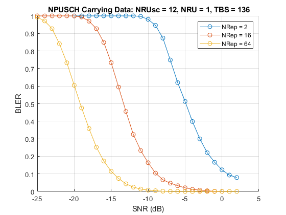
A larger number of transport blocks, numTrBlks should be used to produce meaningful throughput results. The following plot shows the simulation run with numTrBlks set to 5000 for different repetitions, with perfect channel estimator.
Selected Bibliography
3GPP TS 36.211 "Physical channels and modulation"
3GPP TS 36.212 "Multiplexing and channel coding"
3GPP TS 36.213 "Physical layer procedures"
3GPP TS 36.104 "Base Station (BS) radio transmission and reception"
3GPP TS 36.321 "Medium Access Control (MAC); Protocol specification"
3GPP TS 36.331 "Radio Resource Control (RRC); Protocol specification"
3GPP TS 36.300 "Overall description; Stage 2"
O. Liberg, M. Sundberg, Y.-P. Wang, J. Bergman and J. Sachs, Cellular Internet of Things: Technologies, Standards and Performance, Elsevier, 2018.
Helper Functions
The following helper functions are used in this example: