Generate Structured Text Code for State Machine Based Industrial Tank Level Controller
In this example, you use Stateflow® to model and implement a state machine controller to control the level of an industrial tank. Use state machines to design and maintain complex logic, ease handling complex coding constructs, and facilitate fault detection. Use Simulink PLC Coder™ to generate Structured Text code for the state machine controller. Verify the code by generating a test bench and using code traceability to trace the generated code to the corresponding Stateflow chart element.
Model and Implement State Machine Controller
Open the model.
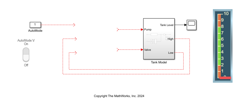
open_system("PumpStateMachine_Start.slx");The model consists of a subsystem named Tank Model that models the tank dynamics, sensors, pump, and valve. You must create and insert a Chart block that models the state machine controller that controls the tank level.

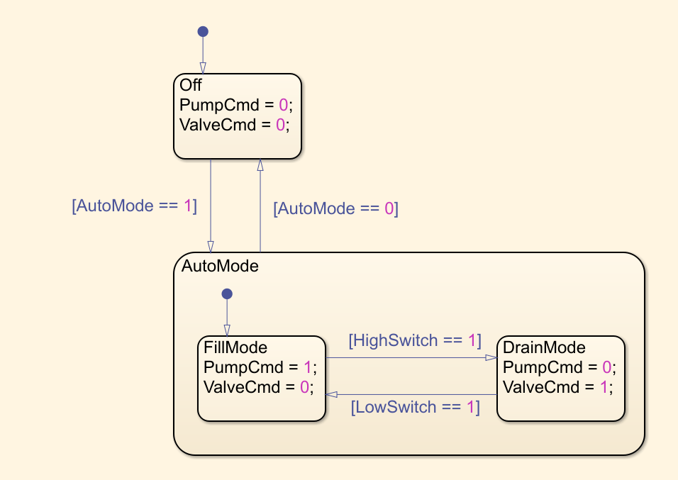
Add a Chart block to the model, add states and transitions, and complete the state machine logic.

In the Modeling tab, in the Design Data section, click Symbols Pane. In the Symbols pane, click the Resolve undefined symbols ![]() button to assign scopes to the data.
button to assign scopes to the data.

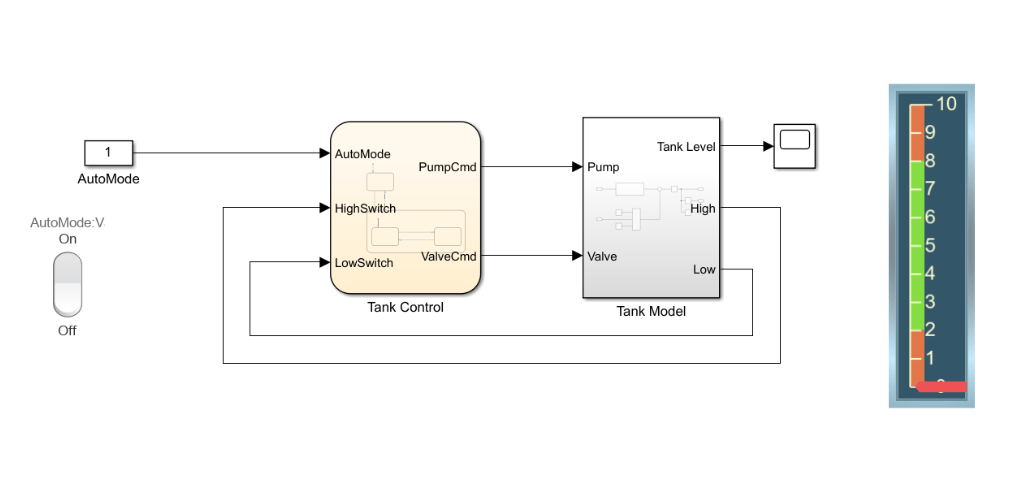
Name the Chart block Tank Control and connect the block inputs and outputs as shown in this image.

Simulate Model and Generate Code for State Machine Controller
When you simulate the model with the AutoMode block in the On position, the red handle indicator in the tank level display slides up and down. When the tank level is at two, the state machine controller turns on the pump, turns off the valve, and fills the tank. When the tank level reaches or exceeds eight, the state machine controller turns on the valve, turns off the pump, and drains the tank. When the AutoMode block is in the Off position, the tank level stays constant. After you verify the operation of your state machine controller, generate Structured Text code for your state machine controller.
To generate code, select the Tank Control chart and, in the Apps tab, select PLC Coder. In the PLC Code tab, click Settings > PLC Code Generation Settings. Change the Target IDE parameter to 3S CoDeSys 3.5. Click OK. Click Generate PLC Code.
Alternatively, you can generate code by using the plcgeneratecode function.
open_system("PumpStateMachine_Complete.slx");
plcgeneratecode("PumpStateMachine_Complete/Tank Control")
### Generating PLC code for 'PumpStateMachine_Complete/Tank Control'.
### Using model settings from 'PumpStateMachine_Complete' for PLC code generation parameters.
### Begin code generation for IDE codesys35.
### Emit PLC code to file.
### Creating PLC code generation report PumpStateMachine_Complete_codegen_rpt.html.
### PLC code generation successful for 'PumpStateMachine_Complete/Tank Control'.
### Generated files:
plcsrc\PumpStateMachine_Complete.xml
View the generated Structured Text code for the state machine controller.
file = fullfile("plcsrc/PumpStateMachine_Complete.st");
coder.example.extractLines(file,"CASE ssMethodType OF","END_CASE",1,1)
CASE ssMethodType OF
    SS_INITIALIZE:
        (* SystemInitialize for Chart: '<Root>/Tank Control' *)
        is_active_c3_Tank := 0;
        is_c3_Tank := Tank_IN_NO_ACTIVE_CHILD;
        is_AutoMode := Tank_IN_NO_ACTIVE_CHILD;
    SS_STEP:
        (* Chart: '<Root>/Tank Control' *)
        (* Gateway: Tank Control *)
        (* During: Tank Control *)
        IF is_active_c3_Tank = 0 THEN
            (* Entry: Tank Control *)
            is_active_c3_Tank := 1;
            (* Entry Internal: Tank Control *)
            (* Transition: '<S1>:2' *)
            is_c3_Tank := Tank_IN_Off;
            (* Outport: '<Root>/PumpCmd' *)
            (* Entry 'Off': '<S1>:1' *)
            (* '<S1>:1:2' PumpCmd = 0; *)
            PumpCmd := 0.0;
            (* Outport: '<Root>/ValveCmd' *)
            (* '<S1>:1:3' ValveCmd = 0; *)
            ValveCmd := 0.0;
        ELSE
            CASE is_c3_Tank OF
                Tank_IN_AutoMode:
                    (* During 'AutoMode': '<S1>:3' *)
                    (* '<S1>:10:1' sf_internal_predicateOutput = AutoMode == 0; *)
                    IF  NOT AutoMode THEN
                        (* Transition: '<S1>:10' *)
                        (* Exit Internal 'AutoMode': '<S1>:3' *)
                        is_AutoMode := Tank_IN_NO_ACTIVE_CHILD;
                        is_c3_Tank := Tank_IN_Off;
                        (* Outport: '<Root>/PumpCmd' *)
                        (* Entry 'Off': '<S1>:1' *)
                        (* '<S1>:1:2' PumpCmd = 0; *)
                        PumpCmd := 0.0;
                        (* Outport: '<Root>/ValveCmd' *)
                        (* '<S1>:1:3' ValveCmd = 0; *)
                        ValveCmd := 0.0;
                    ELSE
                        CASE is_AutoMode OF
                            Tank_IN_DrainMode:
                                (* During 'DrainMode': '<S1>:6' *)
                                (* '<S1>:8:1' sf_internal_predicateOutput = LowSwitch == 1; *)
                                IF LowSwitch THEN
                                    (* Transition: '<S1>:8' *)
                                    is_AutoMode := Tank_IN_FillMode;
                                    (* Outport: '<Root>/PumpCmd' *)
                                    (* Entry 'FillMode': '<S1>:4' *)
                                    (* '<S1>:4:2' PumpCmd = 1; *)
                                    PumpCmd := 1.0;
                                    (* Outport: '<Root>/ValveCmd' *)
                                    (* '<S1>:4:3' ValveCmd = 0; *)
                                    ValveCmd := 0.0;
                                ELSE
                                    (* Outport: '<Root>/PumpCmd' *)
                                    (* '<S1>:6:2' PumpCmd = 0; *)
                                    PumpCmd := 0.0;
                                    (* Outport: '<Root>/ValveCmd' *)
                                    (* '<S1>:6:3' ValveCmd = 1; *)
                                    ValveCmd := 1.0;
                                END_IF;
                            ELSE
                                (* During 'FillMode': '<S1>:4' *)
                                (* '<S1>:7:1' sf_internal_predicateOutput = HighSwitch == 1; *)
                                IF HighSwitch THEN
                                    (* Transition: '<S1>:7' *)
                                    is_AutoMode := Tank_IN_DrainMode;
                                    (* Outport: '<Root>/PumpCmd' *)
                                    (* Entry 'DrainMode': '<S1>:6' *)
                                    (* '<S1>:6:2' PumpCmd = 0; *)
                                    PumpCmd := 0.0;
                                    (* Outport: '<Root>/ValveCmd' *)
                                    (* '<S1>:6:3' ValveCmd = 1; *)
                                    ValveCmd := 1.0;
                                ELSE
                                    (* Outport: '<Root>/PumpCmd' *)
                                    (* '<S1>:4:2' PumpCmd = 1; *)
                                    PumpCmd := 1.0;
                                    (* Outport: '<Root>/ValveCmd' *)
                                    (* '<S1>:4:3' ValveCmd = 0; *)
                                    ValveCmd := 0.0;
                                END_IF;
                        END_CASE;
Trace Generated Code to Blocks
You can trace between Stateflow chart elements and the generated code. To perform tracing, open the code generation report and, in the left pane, click Traceability Report. To open the code generation report, click on PumpStateMachine_Complete_codegen_rpt.html.


Click on the hyperlinks to navigate to the Structured Text code that corresponds to that element. For example, if you click the link corresponding to Transition<S1>:2, the software shows the corresponding Structured Text code.
![]()