Design and Analyze Wideband Multisection Branchline Coupler with Defected Ground Structure
This example shows how to design and analyze a multisection branchline coupler with a defected ground plane in RF PCB Toolbox.
The branchline coupler with one section is a quite fundamental structure and is a very important passive component in many wireless communication systems. These couplers are used to connect with balanced amplifiers, balanced mixers, data modulators, and phase shifters to name a few. However, it causes a narrow bandwidth. You can use a multisection branchline coupler to broaden the bandwidth.
The conventional multisection branchline coupler with a greater number of sections will have the characteristic impedances more than 150 ohm. In a convenctional multisection branchline coupler it is difficult to realize this coupler with higher characteristic impedance. Use defect ground plane (DGS) to reduce the impedances of more than four section branchline coupler.
This example analysis a six-section wideband branchline coupler with DGS for a center frequency of 3 GHz.
Create Multisection Branchline Coupler
Set the variables to create a six section branchline coupler with the dimensions used in [1].
h = 0.76e-3;
N = 6;
PL = 12e-3;
PW = 1.88e-3;
SeriesArmW = 1.88e-3;
SeriesArmL = 16.98e-3;
ShuntArmW = 0.2e-3;
ShuntArmL = 18.37e-3;
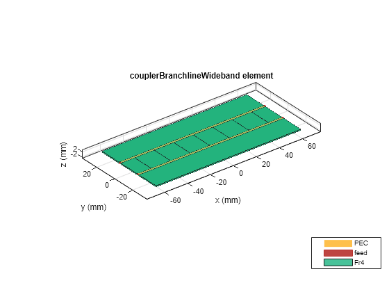
Use the couplerBranchlineWideband object to create the six section branchline coupler and visualize it.
object = couplerBranchlineWideband(NumSections=N);
substrate = dielectric("Name",'Fr4',"EpsilonR",4.4,"LossTangent",0.027, ...
    "Thickness",h,"FrequencyModel","Constant");
object.Substrate = substrate;
object.Height = h;
object.PortLineLength = PL;
object.PortLineWidth = PW;
object.SeriesArmWidth = SeriesArmW;
object.SeriesArmLength = SeriesArmL;
object.ShuntArmWidth = ShuntArmW;
object.ShuntArmLength = ShuntArmL;
figure; show(object);
Create Branchline Coupler with DGS
Use the dgs method to create a DGS. The dgs method takes the catalog and the respective shape for creating the defected ground as an input.
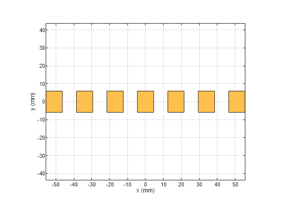
Set the variables to create the rectangular shape that forms the defected ground.
dgsL = 9.1e-3;
dgsW = 11.9e-3;
Create the rectangular shape centered at each shunt arm of the multisection branchline coupler with Length as dgsL and Width as dgsW respectively and visualize it.
% Rectangle shape below the shunt arm centered at (0,0)
rectCentre = traceRectangular("Length",dgsL,"Width",dgsW);

% Rectangle shapes below the left shunt arm from the center (0,0)
rect2 = traceRectangular("Length",dgsL,"Width",dgsW,"Center",[-16.98e-3 0]);
rect3 = traceRectangular("Length",dgsL,"Width",dgsW,"Center",[-33.96e-3 0]);
rect4 = traceRectangular("Length",dgsL,"Width",dgsW,"Center",[-50.94e-3 0]);

rectLeft = cell(1,N/2);
for i = 1: N/2
    rectLeft{i} = traceRectangular("Length",dgsL,"Width",dgsW,"Center",[-(i)*SeriesArmL 0]);
end

rectRight = cell(1,N/2);
for i = 1: N/2
    rectRight{i} = traceRectangular("Length",dgsL,"Width",dgsW,"Center",[(i)*SeriesArmL 0]);
end

rect = rectCentre+rectLeft{1}+rectRight{1};
for i = 2:1:N/2
    rect =rect+rectLeft{i}+rectRight{i};
end

shape = {rect};
figure; show(shape{1});
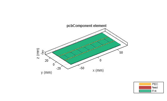
Use the dgs method with catalog and shape as the input and visualize the multisection coupler.
pcbobj = dgs(object,shape);
figure; show(pcbobj);
Manually mesh the structure using mesh function.
The lambda at center frequency is 0.047 m. Set MaxEdgeLength as lambda/8, since eight triangles per lambda are enough to simulate the structure.
Where, lambda is:
lambda = c/(freq*sqrt(epsilonR));
Here, c is the speed of light, freq is 3 GHz and epsilonR is 4.4.
lambda =
0.0477
lambda = 0.0477
figure; mesh(pcbobj,'MaxEdgeLength',lambda/8);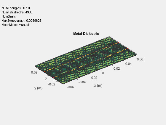
Use the sparameters function to calculate the s-parameters for the above structure and plot it using rfplot function. The frequency range for the simulation is taken as 0.5 GHz to 5 GHz.
sparam = sparameters(pcbobj,linspace(0.5e9,5e9,51));
figure; rfplot(sparam)

The simple and efficient design creates a six sectioned branchline coupler with DGS. Observe that the model gives wide bandwidth of 3.52 dB coupling centered at 3 GHz, with return loss and isolation below 10 dB from 1.3 GHz to 4.5 GHz respectively.
Reference
[1]. Ching-Wen Tang, Senior Member, IEEE, Chien-Tai Tseng, Student Member, IEEE, and Ko-Cheng Hsu "Design of Wide Passband Microstrip Branch-Line Couplers With Multiple Sections," IEEE Transactions on Components, Packaging and Manufacturing Technology, vol. 4, no. 7, pp. 1222-1227, July 2014.
Copyright 2022-2025The MathWorks, Inc.