Waveform Reports
The Waveform and Timing window report contains multiple tabs with waveform data and simulation results. The results include syntax errors, analysis warnings and failures, violations of DRC and overshoot rules, waveform quality margins, and eye diagram details.
Waveform Analysis Report Tabs
Waveform Analysis Log
The Waveform Analysis Log tab contains syntax errors in the data and a summary of the waveform analysis failures.
Waveform Summary
The Waveform Summary tab summarizes the errors and violations reported by the Waveform Fatal tab, Waveform Quality tab, and Waveform Overshoot tab. The spreadsheet contains one row per transfer net.
Waveform Fatal
The Waveform Fatal tab contains all fatal waveform processing errors. A fatal error on an edge prevents the app from generating any timing or waveform data for that edge.
Note
This tab only appears if there is a violation.
Waveform Quality
The Waveform Quality tab contains all waveform DRC warnings. A warning indicates that either a waveform DRC rule has been violated or one of the basic waveform transition rules has been broken.
Note
This tab only appears if there is a violation.
Waveform Overshoot
The Waveform Overshoot tab contains all violations of waveform overshoot rules.
Note
This tab only appears if there is a violation.
Waveform Margin by Variation
The Waveform Margin tab contains all salient waveform quality information that appears under the other waveform quality tabs by simulation. For pre-layout, it includes the solution space values. The margins are reported as one row per simulation.
Eye Details
The Eye Details tab contains detailed data on the eye diagram at the receiver for each simulation. This includes eye opening with timing jitter and the outer amplitudes of its envelope. This tab also has the timing points on the simulation where this data was measured. For pre-layout, it includes the solution space values. The eye measurements are reported as one row per node per simulation.
Eye Rollups
The Eye Rollups tab contains the eye diagram, eye opening, jitter and outer height by receiver. It summarizes the eye details for each transfer net.
Waveform Margin by TNET
The Waveform Margin by TNET tab contains waveform quality information that appears under the other waveform quality tabs, organized by simulation and rolled up for each transfer net. The margins are reported as one row per transfer net.
Derating Details
The Derating Details tab contains the slew rates and the etch delays (raw and derated). The slew rate parameters are measured as:
Slew Rate (rising) — Last crossing of
Vin_DC_Lowto first crossing ofVin_AC_High.Slew Rate (falling) — Last crossing of
Vin_DC_Highto first crossing ofVin_AC_Low.DC Slew Rate (rising) — Last crossing of
Vin_DC_Lowto first crossing ofVin_DC_High.DC Slew Rate (falling) — Last crossing of
Vin_DC_Highto first crossing ofVin_DC_Low.AC Slew Rate (rising) — Last crossing of
Vmeasto first crossing ofVin_AC_High.AC Slew Rate (falling) — Last crossing of
Vmeasto first crossing ofVin_AC_Low.
Mask Results
The Parallel Link Designer app processes the mask data waveforms individually
and combine them to create the mask reports. mask does not have fixed measurement
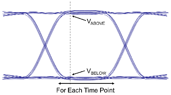
thresholds. All measurements are relative to Vref. The app determines
Vref for each waveform and then combines them for each memory
device.
| Mask Report Column | Definition | Graphical Representation |
|---|---|---|
| # Eyes Rolled up For Margin |
| |
| # Eyes Rolled up For Vref |
| |
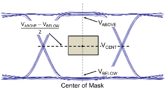
| Trained Vref (V) | Halfway between the smallest Mask High Boundary and largest Mask Low Boundary of all eye rolled up for VREF. | |
| Trained Vref (%) | Defined as: | |
| Trained Eye Height ViVW Margin (V) | The smallest margin from the mask centered at Trained VREF to the Eye High Boundary and Eye Low Boundary. | |
| Trained Eye Width TiVW Margin (ns) | The smallest margin from the mask centered at Trained VREF to the Eye Left Boundary and Eye Right Boundary. | |
| VREF (V) |
|
|
| VREF (%) | Defined as: | |
| Eye Height (V) | The maximum inner eye height for this waveform. | |
| Eye Width (ns) | The maximum inner eye width for this waveform. | |
| VCENT (V) |
|
|
| Eye Width at VCENT (ns) | The width of the eye at VCENT for a waveform. | |
VCENT
| The Eye Width at VCENT excluding the
TiVW. TiVW represents the receiver mask
width. | |
Edge Pulse Width TiPW (ns) | The smallest pulse width measured at VREF. | |
Edge Pulse Width TiPW Margin (ns) | The Edge Pulse Width TiPW (ns) excluding the
TiPW. TiPW represents the minimum pulse
width at VCENT. | |
Edge VIHL_AC Low Margin (V) |
| |
Edge VIHL_AC High Margin (V) |
| |
Edge Min Slew Rate SRIN_diVW (V/ns) |
| |
Edge Max Slew Rate SRIN_diVW (V/ns) |
| |
Edge Min Slew Rate SRIN_diVW Margin (V/ns) | Minimum slew rate (Edge Min Slew Rate SRIN_diVW (V/ns))
excluding the SRIN_diVW_Min. SRIN_diVW_Min
represents the minimum input slew rate over the peak-to-peak height of the receiver
mask. | |
Edge Max Slew Rate SRIN_diVW Margin (V/ns) | Maximum slew rate (Edge Max Slew Rate SRIN_diVW (V/ns))
excluding the SRIN_diVW_Max. SRIN_diVW_Max
represents the maximum input slew rate over the peak-to-peak height of the receiver
mask. | |
Edge Min SRIN_sr2 (V/ns) |
| |
Edge Max SRIN_sr2 (V/ns) |
| |
Edge Min SRIN_sr2 Margin (V/ns) | Minimum slew rate (Edge Min | |
Edge Max SRIN_sr2 Margin (V/ns) | Maximum slew rate (Edge Max | |
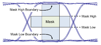
| Mask Low (V) |
|
|
| Mask High (V) |
| |
| Mask Low Boundary (V) | The lowest voltage the bottom of the mask could have and still fit in the eye. | |
| Mask High Boundary (V) | The highest voltage the bottom of the mask could have and still fit in the eye. | |
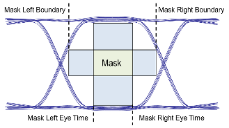
| Mask Left Eye Time (ns) |
|
|
| Mask Right Eye Time (ns) |
| |
| Mask Left Boundary (ns) | The earliest eye time the left edge of the mask could have and still fit in the eye. | |
| Mask Right Boundary (ns) | The latest eye time the right edge of the mask could have and still fit in the eye. | |
| Eye Height ViVW Margin (V) |
| |
| Eye Width TiVW Margin (ns) |
| |
| AC Inner Eye Height (V) | Difference between the largest voltage in mask range and the smallest voltage in mask range. | |
| AC Inner Eye Total Margin (V) | AC Inner Eye Height excluding VIHL_AC. | |
| AC Eye Min (V) | The smallest voltage in mask range. | |
| AC Eye Max (V) | The largest voltage in mask range. | |
| Eye Start Sim Time (ns) | Simulation time of the start of the waveform data used to create the eye. | |
| Eye Stop Sim Time (ns) | Simulation time of the end of the waveform data used to create the eye. |