Create Test Harness to Generate Function Calls
After you create a model component to initialize, reinitialize, reset, and terminate the state of blocks (see Using Initialize, Reinitialize, Reset, and Terminate Functions), you can place the model in a simulation test harness. A test harness is a Simulink® model that you use to develop, test, and debug a model component.
To create the test harness, reference the export-function model containing the model component in a new model, and then add a Stateflow® chart to model a function-call event scheduler.
Reference the Export-Function Model
The export-function model contains the model component for testing. To create the export-function model, see Create an Export-Function Model.
Create a Simulink model. Save this model with the name
Test_Model.Set configuration parameters for Solver Type to
Fixed-step, Solver toauto, and Fixed-step size to1.Add a Model block. Double-click the Model to open the Block Parameters dialog box. In the Model name text box, enter the name of your export-function model. In this example, enter
Model02.Test the referenced model component by connecting a Function-Call Generator block to the
Runport. Connect a Constant block to theSignal Inport and a Scope block to theSignal Outport.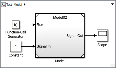
Run a simulation to verify your model simulates correctly from the parent model. When the model is simulated without function-call event ports, the Initialize Function block executes at the beginning of a simulation and the Terminate Function block executes at the end of the simulation.
Expose function-call input ports on the Model block. Double-click the Model block to open the Block Parameters dialog box. In the Block Parameters dialog box, select Show model initialize port, Show model reset port, and Show model terminate port.
Delete the Function-Call Generator block and update the model by pressing Ctrl+D.
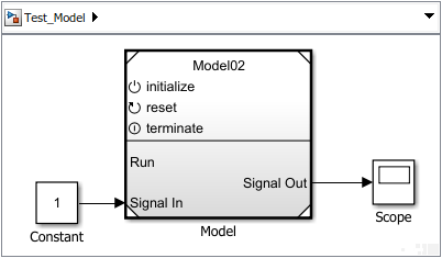
When you activate the initialize function-call input port on a Model block, the model has to receive an initialize function call on the
initializeport before it can execute. The reception of a function call triggers the execution of the default model initialize routine, and then the execution of the Initialize Function block contents.The reception of a function call on the
Resetport triggers the execution of the Reset Function block contents.The reception of a function call on the
Terminateport triggers the execution of the Terminate Function block contents, and then the execution of the default model terminate routine. The model then stops running. To execute the model again, you have to reinitialize the model by sending a function-call event to theinitializeport.
Model an Event Scheduler
Use a Stateflow chart to model an event schedule and generate the initialize and terminate function call signals.
Add a Stateflow chart. Click the model diagram and start typing
Chart. From the search list, select .
.Open the chart and add two state blocks, one above the other.
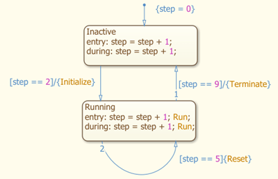
Add a default transition and connect it to the top state block. Edit the label:
{step = 0}Add a transition from the top block to the bottom block. Edit the label:
[step == 2]/{Initialize}Add a transition from the bottom block and back to the bottom block. Edit the label:
[step == 5]/{Reset}Add a transition from the bottom block to top block. Edit the label:
[step == 9]/{Terminate}Edit the content of the top block:
Inactive
entry: step = step + 1;
during: step = step + 1;
Edit the content of the bottom block:
Running
entry: step = step + 1; Run;
during: step = step + 1; Run;
Connect Chart to Test Model
Create function-call output ports on the chart to control and run the model component.
Open Model Explorer. On the Modeling tab and from the Design section, select Model Workspace
 .
.Create index variable. From the menu, select Add > Data. In the Data dialog box, enter
Stepfor the Name.Create function-call output ports. For each function-call event you create, select Add > Event and in the Event dialog box, enter, and select the following values.
Enter in Event Text Box Set Scope Set Trigger InitializeOutput to SimulinkFunction callResetOutput to SimulinkFunction callTerminateOutput to SimulinkFunction callRunOutput to SimulinkFunction callNavigate to the top level of the model. Connect the
Initialize,Reset,Terminate, andRunports on the chart to theinitialize,reset,terminate, andRuninput ports on the Model block.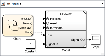
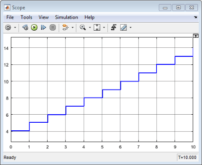
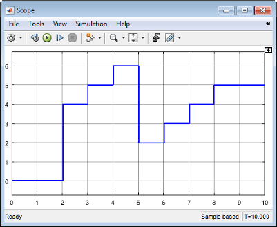
Run a simulation.
The model cannot execute until the second time step, when the block state is initialized to 4. At the fifth time step, a reset function call to the reset port triggers the Reset Function block to execute. At the ninth time step, the subsystem stops executing, and the block state remains constant.
If the model receives a function call to run before an initialize function call, a simulation error occurs.
Note
You can create the same test harness using Simulink
Test™. In this example, Simulink
Test uses a Stateflow chart to create the test harness scheduler and source. For more
information, see Stateflow Chart as Test Harness Scheduler and Source (Simulink Test). To set up
Model02 for Simulink
Test, place the input signal source (connected to the Signal
In port) at the root level of Model02 and connect
the source to the function-call subsystem. To visualize the output, connect a
Scope block to the output signal of
Model02.
See Also
Initialize Function | Reinitialize Function | Reset Function | Terminate Function | Event Listener | State Reader | State Writer | Parameter Writer
Topics
- Using Initialize, Reinitialize, Reset, and Terminate Functions
- Initialize and Reset Parameter Values
- Use Stateflow Chart for Test Harness Inputs and Scheduling (Simulink Test)