Main Content

Coupled Lines (Three-Phase)

Magnetically couple three-phase lines

  • Coupled Lines (Three-Phase) block

Libraries:
Simscape / Electrical / Passive / Lines

Description

The Coupled Lines (Three-Phase) block models three magnetically coupled lines. Each line has a self-inductance, series resistance, and parallel conductance. In addition, there is a mutual inductance and mutual resistance between each pair of lines.

Use this block when the magnetic coupling in a three-phase network is nonnegligible. These effects are most prominent when:

  • The lines are parallel and close together.

  • The self-inductances of the lines are high.

  • The AC frequency of the network is high.

To model magnetic coupling of a single pair of lines, use the Coupled Lines (Pair) block. To model capacitive coupling between the lines, use the Transmission Line block.

Equivalent Circuit

The equivalent circuit shows the coupling between two arbitrary phases i, and j. The block models the magnetic coupling using such an equivalent circuit between each of the three phases a, b, and c.
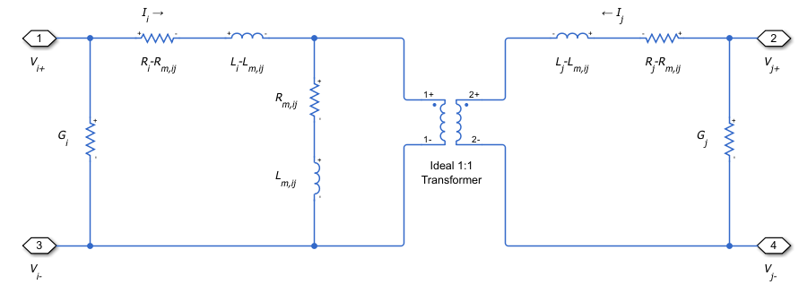
Here:

  • Ri and Rj are the series resistances of lines i and j, respectively.

  • Li and Lj are the self-inductances of lines i and j, respectively.

  • Rm is the mutual resistance between the two lines. You can use this parameter to account for losses in a common return path.

  • Lm,ij is the mutual inductance between lines i and j, respectively.

  • Gi and Gj are the leakage conductances of lines i and j, respectively.

  • Vi and Vj are voltage drops across lines i and j, respectively.

  • Ii and Ij are the currents through the resistors Ri-Rm and Rj-Rm, respectively.

Equations

The defining equation for this block is:

V=[RaRmRmRmRbRmRmRmRc]I+[LaLm,abLm,acLm,abLbLm,bcLm,acLm,bcLc]dIdt,

where:

V=[VaVbVc],

I=[IaIbIc].

Ia, Ib, and Ic are, in general, not equal to the currents in lines a, b, and c. These terminal currents make up the vector:

Itotal=I+[Ga000Gb000Gc]V.

Inductive Coupling

To quantify the strength of the coupling between the two lines, you can use a coupling factor or coefficient of coupling k. The coupling factor relates the mutual inductance to the line self-inductances:

Lm,ij=kLiLj.

This coupling factor must fall in the range 1<k<1, where a negative coupling factor indicates a reversal in orientation of one of the coils. The magnitude of k indicates:

  • |k|=0 — There is no magnetic coupling between the two lines.

  • 0<|k|<0.5 — The two lines are loosely coupled and mutual magnetic effects are small.

  • 0.5|k|<1 — The two lines are strongly coupled and mutual magnetic effects are large.

Mutual Resistance

If the three lines share a common return path, you can model the resistance of this return path using the Mutual resistance parameter Rm. This workflow is equivalent to setting the Mutual resistance to zero and explicitly modeling the return path resistance Rm, as shown in this diagram.

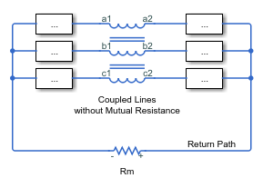
If the three lines do not share a common return path, set the mutual resistance parameter to zero and model each of the return resistances explicitly.

Ports

Conserving

expand all

Expandable three-phase electrical conserving port associated with the positive terminals of lines a, b, and c.

Dependencies

To enable this port, set Modeling option to Composite three-phase ports

Expandable three-phase electrical conserving port associated with the negative terminals of lines a, b, and c.

Dependencies

To enable this port, set Modeling option to Composite three-phase ports

Electrical conserving port associated with the positive terminal of line a.

Dependencies

To enable this port, set Modeling option to Expanded three-phase ports

Electrical conserving port associated with the negative terminal of line a.

Dependencies

To enable this port, set Modeling option to Expanded three-phase ports

Electrical conserving port associated with the positive terminal of line b.

Dependencies

To enable this port, set Modeling option to Expanded three-phase ports

Electrical conserving port associated with the negative terminal of line b.

Dependencies

To enable this port, set Modeling option to Expanded three-phase ports

Electrical conserving port associated with the positive terminal of line c.

Dependencies

To enable this port, set Modeling option to Expanded three-phase ports

Electrical conserving port associated with the negative terminal of line c.

Dependencies

To enable this port, set Modeling option to Expanded three-phase ports

Parameters

expand all

Whether to model composite or expanded three-phase ports.

Composite three-phase ports represent three individual electrical conserving ports with a single block port. You can use composite three-phase ports to build models that correspond to single-line diagrams of three-phase electrical systems.

Expanded three-phase ports represent the individual phases of a three-phase system using three separate electrical conserving ports.

Main

Specify how to parameterize the impedance of the three lines:

Balanced impedance

Specify the same series resistance, series inductance, and parallel leakage conductance for all lines.

General impedance

Specify the series resistance, series inductance, and parallel leakage conductance separately for each line.

Self-inductance of line a. This value must be greater than zero.

Dependencies

To enable this parameter, set Parameterization to General impedance.

Self-inductance of line b. This value must be greater than zero.

Dependencies

To enable this parameter, set Parameterization to General impedance.

Self-inductance of line c. This value must be greater than zero.

Dependencies

To enable this parameter, set Parameterization to General impedance.

Self-inductance of lines a, b, and c. This value must be greater than zero.

Dependencies

To enable this parameter, set Parameterization to Balanced impedance.

Mutual inductance between lines a and b. If you know the coupling factor, set this value to kLaLb. To have a physically realizable mutual inductance, this value must satisfy:

LaLb<Lm,ab<LaLb.

Dependencies

To enable this parameter, set Parameterization to General impedance.

Mutual inductance between lines b and c. If you know the coupling factor, set this value to kLbLc. To have a physically realizable mutual inductance, this value must satisfy:

LbLc<Lm,bc<LbLc.

Dependencies

To enable this parameter, set Parameterization to General impedance.

Mutual inductance between lines a and c. If you know the coupling factor, set this value to kLaLc. To have a physically realizable mutual inductance, this value must satisfy:

LaLc<Lm,ac<LaLc.

Dependencies

To enable this parameter, set Parameterization to General impedance.

Mutual inductance between each pair of lines. If you know the coupling factor, set this value to kL, where L is the series inductance of each of the lines. To have a physically realizable mutual inductance, this value must satisfy:

L<Lm<L.

Dependencies

To enable this parameter, set Parameterization to Balanced impedance.

Resistance

Series resistance of line a. This value must be greater than or equal to zero.

Dependencies

To enable this parameter, set Parameterization to General impedance.

Series resistance of line b. This value must be greater than or equal to zero.

Dependencies

To enable this parameter, set Parameterization to General impedance.

Series resistance of line c. This value must be greater than or equal to zero.

Dependencies

To enable this parameter, set Parameterization to General impedance.

Series resistance of lines a, b, and c. This value must be greater than or equal to zero.

Dependencies

To enable this parameter, set Parameterization to Balanced impedance.

Mutual resistance between each pair of lines. This value must be greater than or equal to zero. Use this value to account for losses in a common return path.

Parallel leakage conductance of line a. This value must be greater than or equal to zero.

Dependencies

To enable this parameter, set Parameterization to General impedance.

Parallel leakage conductance of line b. This value must be greater than or equal to zero.

Dependencies

To enable this parameter, set Parameterization to General impedance.

Parallel leakage conductance of line a. This value must be greater than or equal to zero.

Dependencies

To enable this parameter, set Parameterization to General impedance.

Parallel leakage conductance of lines a, b, and c. This value must be greater than or equal to zero.

Dependencies

To enable this parameter, set Parameterization to Balanced impedance.

Extended Capabilities

C/C++ Code Generation
Generate C and C++ code using Simulink® Coder™.

Version History

Introduced in R2018a