Detect and Match Local Features Between Image Frames Using Android Device
This example shows how to use the Simulink® Support Package for Android® Devices to determine the geometric transformation between a pair of images. When one image frame is distorted relative to another by rotation or scale, you can find out the rotation angle and scale factor to recover the original image.
Prerequisites
Ensure that you install OpenCV version 4.5.2 from the Hardware Setup window.
For more information on how to use the Simulink Support Package for Android Devices to run a Simulink model on your Android device, see Getting Started with Android Devices.
For more information on how to get started with computer vision applications on your Android device, see Get Started with Computer Vision Applications Using Android Device.
Required Hardware
Android device such as a phone or tablet
USB cable
Hardware Setup
Connect your Android device to the host computer using the USB cable. Set up your Android device using the Hardware Setup. For more information, see Hardware Setup.
Configure Simulink Model and Calibrate Parameters
Open the androidVisionFeaturePoints Simulink model.
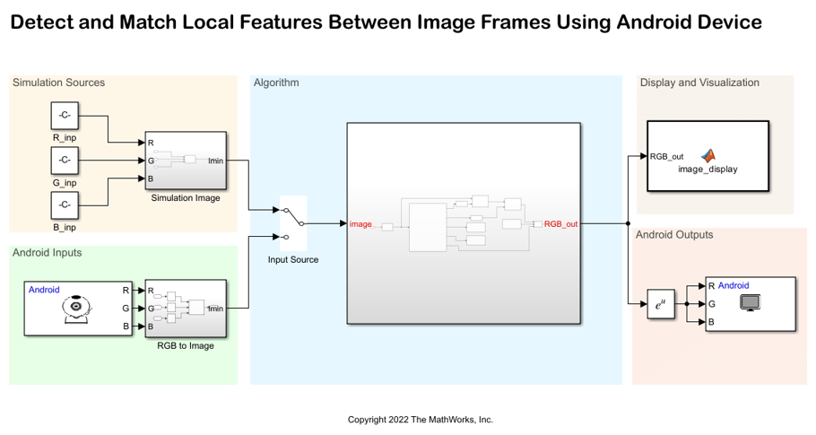
For more information on Simulation Sources, Android Inputs, Display and Visualization, and Android Outputs area, see Get Started with Computer Vision Applications Using Android Device.
Algorithm

The im2gray
The code in the visionRecovertformCodeGeneration_kernel MATLAB Function block uses these steps to find the rotation angle and scale factor between the original and distorted image, and to transform the distorted image to recover the original image.
Step 1: Find Matching Features between Images — Detect Speeded-Up Robust Features (SURF) features in both, the original image and the distorted image, extract interest point descriptors, find matching features, and retrieve locations of corresponding points of each image.
Step 2: Estimate Transformation — Find a transformation corresponding to the matching point pairs using the statistically robust M-estimate SAmple Concensus (MSAC) algorithm.
Step 3: Solve for Scale and Angle — Recover scale and angle of images using the geometric transform, tform. The recovery scale and angle of images are displayed on the Android application.
Step 4: Recover Original Image — Recover the original image by applying reverse transform on the distorted image. The algorithm uses the recovery scale and angle of the images as mentioned in step 3.
On the original input image, the Draw Markers (Computer Vision Toolbox) block draws plus shaped markers by overwriting the pixel values in the image. Whereas, on the distorted input image, the block draws square shaped markers.
Use the Bypass Button block to display a button widget on your Android application. This button toggles the output between the restored image and the image that is marked with feature points.
Deploy Simulink Model on Android Device
1. In the Algorithm area of the Simulink model, position the Manual Switch to receive output from the Android Inputs area.
2. On the Hardware tab of the Simulink model, in the Mode section, click Run on board. In the Deploy section, click Build, Deploy & Start. The androidVisionFeaturePoints application launches automatically on your Android device.
3. Point the camera of your Android device towards an object. Observe the plus and square markers on the image. Also, observe the Angle Recovered and Scale Recovered parameters on the application.

4. Press Byapss and observe the restored image output on the application.

See Also
You can also select a web site from the following list:
Americas
- América Latina (Español)
- Canada (English)
- United States (English)
Europe
- Belgium (English)
- Denmark (English)
- Deutschland (Deutsch)
- España (Español)
- Finland (English)
- France (Français)
- Ireland (English)
- Italia (Italiano)
- Luxembourg (English)
- Netherlands (English)
- Norway (English)
- Österreich (Deutsch)
- Portugal (English)
- Sweden (English)
- Switzerland
- United Kingdom (English)