Code Verification and Validation with Processor-in-the-Loop (PIL) Simulation
This example shows you how to use Simulink® Coder™ Support Package for code verification and validation with PIL using STMicroelectronics® Nucleo Boards. The PIL feature requires Embedded Coder®.
In this example, you will learn how to configure a Simulink model to run Processor-in-the-Loop (PIL) simulations. In a PIL simulation, the generated code runs on the Nucleo boards. The results of the PIL simulation are transferred to Simulink to verify the numerical equivalence of the simulation and the code generation results. The PIL verification process is a crucial part of the development cycle to ensure that the behavior of the deployment code matches the design.
This example introduces the Simulink code generation and verification workflow by showing you how to configure a Simulink model to run PIL simulations on the STMicroelectronics Nucleo board. This example is pre-configured to run on Nucleo F401RE board. You can configure this model for other supported Nucleo boards by selecting them as the "Hardware board" on the Hardware Implementation pane of the Model Configuration Parameters.
Prerequisites
We recommend completing the Getting Started with Simulink Coder Support Package for STMicroelectronics Nucleo Boards example.
Required Hardware
To run this example you will need the following hardware:
Supported STMicroelectronics Nucleo board
USB type A to Mini-B cable
Choosing a Communication Interface for PIL Simulation
The Nucleo boards supports interface that does not require any additional cables or hardware besides a USB type A to Mini-B cable used to connect the STMicroelectronics Nucleo board to the host computer.
1. Open the TopModelPIL.slx model.
2. Open the Modeling tab and press CTRL+E to open Configuration Parameters dialog box.
3. Go to Hardware Implementation > Target Hardware Resources > PIL > Serial port, enter the COM port of the serial interface on Windows.
Open Devices manager
Click the Ports tab
4. Look for STMicroelectronics STLink Virtual COM Port and copy the COM port number to the Simulink model following the steps below:


Verifying Top Model Code with PIL
This example shows how to verify the generated code for a model by running a PIL simulation. With this approach:
You can verify code generated for a top model
You must configure the model to load test vectors or stimulus inputs from the MATLAB workspace
You can easily switch the entire model between normal and PIL simulation mode
1. Open the TopModelPIL.slx model. This model is configured for the STM32 Nucleo F401RE target. You can run the model for other Nucleo targets, by changing the Hardware board to supported nucleo board in the Configuration Parameters > Hardware Implementation pane.
2. Choose a PIL communication interface by following the steps in Task 1 above.
3. Go to Apps tab and search SIL/PIL.

4. Select Processor-in-the-Loop(PIL) from the SIL/PIL Mode drop-down and click Run Verification.
5. When the PIL simulation is completed, a logsOut variable is created in the base workspace. The logsOut data contains PIL simulation results. You can access the logged data for signals count_a and count_b using the following commands:
count_a = get(logsOut,'count_a');
count_a.Values.Data
count_b = get(logsOut,'count_b');
count_b.Values.Data

Verifying Referenced Model Code with PIL
This example shows how to verify the generated code for a referenced model by running a PIL simulation. With this approach:
You can verify code generated for referenced models
You must provide a test harness model to provide a test vector or stimulus inputs
You can easily switch a Model block between normal and PIL simulation mode
1. Open the ModelPILBlock.slx model. This model is configured for STM32 Nucleo F401RE target. You can run the model for other Nucleo targets, by changing the Hardware board to supported nucleo board in the Configuration Parameters > Hardware Implementation pane. The model contains two Model blocks that both point at the same referenced model. Note, that the Hardware board change has to be made in the reference model also by double clicking on counterA or counterB to open the refernced model and following the steps above. You will configure one of the Model blocks to run in PIL simulation mode and the other in normal mode.
2. Choose a PIL communication interface by following the steps in Task 1 above.
3. Configure and run CounterA Model block in PIL simulation mode by following steps below:
a. Right click on block CounterA and select Block Parameters (ModelReference)

b. In the CounterA block parameter, Select Simulation mode as Processor-in-the-Loop(PIL)

c. Go to Simulation tab and Run
4. When the model starts running, Scope1 displays the PIL simulation output running on the Nucleo board while Scope2 shows the normal mode simulation output.

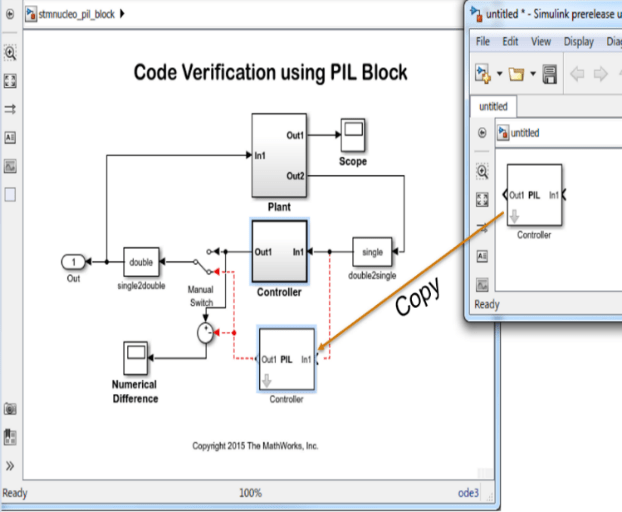
Verifying the Generated Code for a Subsystem Using a PIL Block
This example shows how to use a PIL block for subsystem code verification. With this approach:
You can verify the code generated for a subsystem
You must provide a test harness model to supply a test vector or stimulus inputs
You must swap your original subsystem with a generated PIL block; you should be careful to avoid saving your model in this state as you would lose your original subsystem
1. Open the PILBlock.slx model. This model is configured for the STM32 Nucleo F401RE target. You can run the model for other Nucleo targets, by changing the Hardware board to supported nucleo board in the Configuration Parameters > Hardware Implementation pane.
The objective here is to create a PIL block out of the Controller subsystem that you will run on the Nucleo board.
2. Choose a PIL communication interface by following the steps in Task 1 above.
3. Enable PIL by following steps:
a. Go to the Modeling tab and press Ctrl+E to open Configuration Parameters dialog box.
b Go to Code Generation > Verification > Advanced parameters and select PIL.

4. Create a PIL block for the Controller subsystem by following below steps:
a. Right click on the Controller subsystem and select Deploy this Subsystem to Hardware.

b. In the Build code for SubsystemController dialog box, click Build.

5. Run PIL simulation by following below steps:
6. The generated executable is copied to the drive letter in Windows of the board.
7. You can switch between the original and PIL block subsystems by double clicking on the Manual Switch block. Double click on the Numerical Differences block to see the difference between the simulated Controller subsystem and the PIL block running on the Nucleo board.
You can also select a web site from the following list:
Americas
- América Latina (Español)
- Canada (English)
- United States (English)
Europe
- Belgium (English)
- Denmark (English)
- Deutschland (Deutsch)
- España (Español)
- Finland (English)
- France (Français)
- Ireland (English)
- Italia (Italiano)
- Luxembourg (English)
- Netherlands (English)
- Norway (English)
- Österreich (Deutsch)
- Portugal (English)
- Sweden (English)
- Switzerland
- United Kingdom (English)