Getting Started with Connected I/O for PX4 Host Target
This example shows you how to enable and use Connected I/O simulation to read data from PX4 Host Target during normal mode simulation.
Introduction
The UAV Toolbox Support Package for PX4® Autopilots enables you to communicate with the PX4 Host Target during normal mode simulation by enabling Connected I/O. Connected I/O is not based on Simulink® code generation, hence Embedded Coder® license is not required to use Connected I/O simulation. For more information and list of supported blocks see Communicate with Hardware Using Connected I/O.
In this example, you will:
Enable Connected I/O simulation
Observe the accelerometer and GPS data from PX4 Host Target by running the model in Normal mode simulation
Prerequisites
If you are new to Simulink, watch the Simulink Quick Start video.
Perform the initial Setup and Configuration of the support package using the Hardware Setup screens. In the Hardware Setup screens, ensure that you select PX4 Host Target for PX4 Autopilot board option.
Task 1 - Configure and Run a Model to Read Accelerometer Data Using Accelerometer Block
In this task, you will configure a Simulink model to read accelerometer sensor data from PX4 Host Target using an Accelerometer block. You will also observe the data over Connected I/O simulation.
1. From the MATLAB toolstrip, select Home > New > Simulink Model to to open the Simulink Start Page. Click Blank Model to launch a new Simulink model.
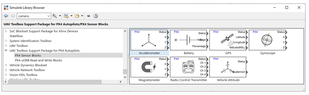
2. On the Simulation tab, click Library Browser. In the Library Browser, select UAV Toolbox Support Package for PX4 Autopilots > PX4 Sensor Blocks, and then add an Accelerometer block to the model.
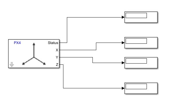
3. In the Library Browser, Select Simulink >, then drag and drop four Display blocks to the model. Connect the three outputs of the Accelerometer block to the three Display blocks. Connect the Status output to the fourth Display block as shown in the image below.
4. In the Modeling tab, click Model Settings to open the Configuration Parameters dialog box.
5. In the Configuration Parameters dialog box, select Hardware Implementation.
Verify that the Hardware board parameter is set to
PX4 Host Target.

6. On the Modeling tab, set the StopTime to inf.
7. To run this model in the Connected I/O mode, on the Hardware tab, in the Mode section, select Connected IO and then click Run with IO.

Ensure the PX4 Host target and jMAVSim Simulator launches.
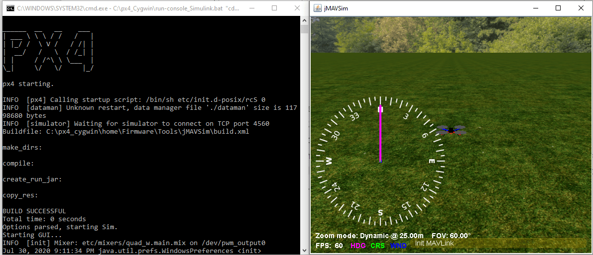
Once the Simulation begins, you can view the values in the display. Z accel = -9.8 (acceleration value due to gravity. This is because the drone is on the ground and in horizontal position).

8. Stop the simulation after observing values. Do not close the PX4 Host Target and jMAVSim windows.
Task 2 - Add PX4 GPS Block to the Configured Model to Read GPS Values
Since Connected I/O is not based on Simulink code generation, the PX4 Host Target launched during Task 1 is independent of the model. If you add or delete blocks or modify the model, Simulink connects to the already launched PX4 Host Target and reads data for updated model. For example, add PX4 GPS block to the earlier configured model in task 1 and run the simulation again.
1. On the Simulation tab, click Library Browser. In the Library Browser, Select UAV Toolbox Support Package for PX4 Autopilots > PX4 Sensor Blocks, then add a GPS block to the model.
2. In the Library Browser, Select Simulink and then drag and drop four Display blocks to the model. Connect the three outputs of the GPS block to the three Display blocks. Connect the Status output to the fourth Display block as shown in the image below.

The GPS values displayed are of Zurich, Switzerland. These GPS values are the default values provided in GPS simulator module of PX4.
Task 3 - Run Connected I/O Simulation Close to Real-Time Using Simulation Pacing Option
In tasks one and two, Simulink runs slower than the wall clock. This section helps you to run the Connected I/O simulation close to real-time using Simulation Pacing option. Perform these steps to run the model using Simulation Pacing option.
1. On the Hardware tab, select Simulation Pacing.

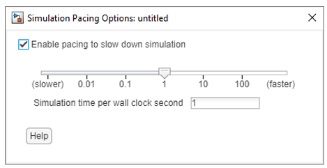
2. In the Simulation Pacing Options dialog, select Enable pacing to slow down simulation. On enabling, the specified pace gets automatically applied to the simulation. Set the value for Simulation time per wall clock second as 1.
3. Along with enabling Simulink pacer on and setting the Simulation time per wall clock second as 1, sample time for the block has to be chosen specifically for getting close to real-time simulation. There is a two-way communication between Simulink and the Host Target while running Connected I/O simulation. This introduces a inherent time overhead for a particular block execution. Thus, there is a specific minimum time required for a block execution. This varies with the machine performance and can be around 15-20 milliseconds. Now the sample time of these blocks should be more than this block execution time for close to real-time connected I/O simulation. Assuming the block Execution time is 20 milliseconds for block, since we have two blocks here, the minimum sample time of the model we can keep to get close to real-time behavior is 20*2 = 40 milliseconds. Set the sample time of the blocks as 40 milliseconds.
4. Simulate the model. Observe that Simulink time is close to wall clock.
The host target does not launch again. Simulink connects to the existing host target launched previously and reads the data.
Other Things to Try
You can use preconfigured Simulink models that helps you to read and write to uORB topics. You can run Connected I/O simulation in the preconfigured models. For more information on uORB blocks, see Getting Started with uORB Blocks for PX4 Autopilots Support Package.
Connected I/O simulation is not suitable for designing closed loop controllers and systems with dynamic feedback, where blocks must run at much higher rate. Hence it is recommended not to try the controller examples with Connected I/O.
You can also select a web site from the following list:
Americas
- América Latina (Español)
- Canada (English)
- United States (English)
Europe
- Belgium (English)
- Denmark (English)
- Deutschland (Deutsch)
- España (Español)
- Finland (English)
- France (Français)
- Ireland (English)
- Italia (Italiano)
- Luxembourg (English)
- Netherlands (English)
- Norway (English)
- Österreich (Deutsch)
- Portugal (English)
- Sweden (English)
- Switzerland
- United Kingdom (English)