Serially Managed DC-DC Power Converter Using C2000
This example shows how to use a serial connection to manage a high-speed, closed-loop DC-DC buck converter control algorithm executing the Texas Instruments® C2000™ processor. In most C2000 microcontroller unit (MCU) families, the MCU executes the hard-realtime portions of the algorithm and uses peripherals, such as ADC and PWM. The MCU also includes one or more low-power, serial communication interfaces (SCI) connections. SCI can be used to connect the C2000 MCU to external systems without the need to use other processors, such as ARM® Cortex®-M, for higher level interfaces, such as network UDP or TCP. This example implements a technique that extends the DC-DC buck converter in the C2000 DC-DC Buck Converter Using MCU. You can apply this technique to any design in which a hard-realtime process executes on the C2000 MCU and requires low-power connectivity using an SCI.
Requirements
Controller with Serial Connection
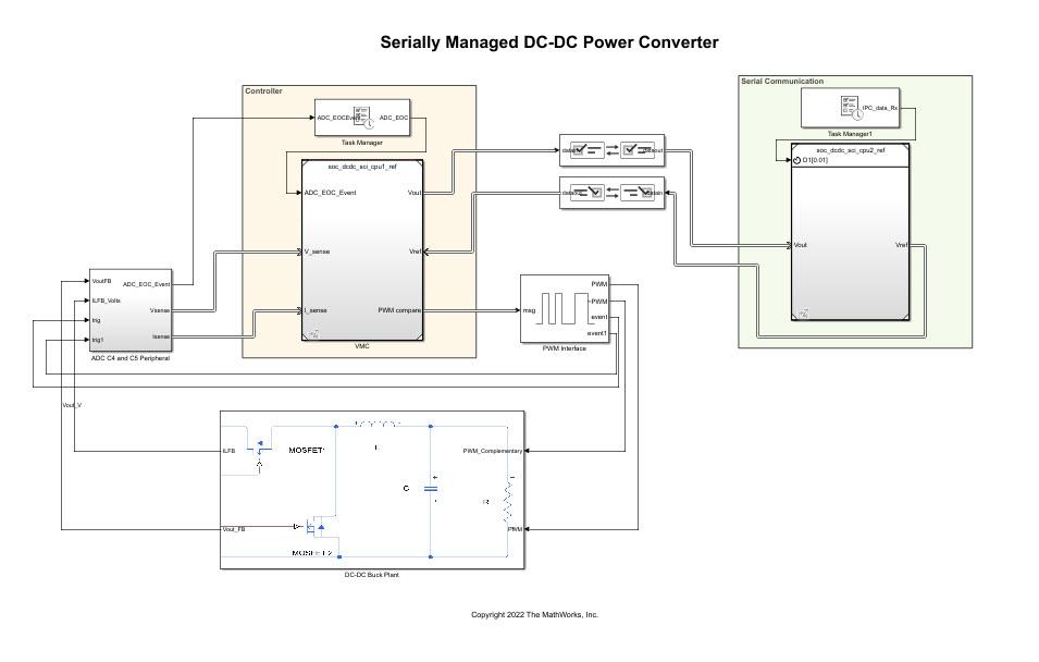
This model shows a DC-DC buck converter with a voltage-tracking control algorithm executing on the first C2000 processor. The second C2000 processor sends the voltage reference signal to the first C2000 processor using an Interprocess Data Read, Interprocess Data Channel, and Interprocess Data Write block triplet. Similarly, the first C2000 processor sends the measured voltage back to the second C2000 processor. Open the soc_dcdc_sci_top model.

For more information about designing the closed-loop control algorithm and simulating the power daughter board, see C2000 DC-DC Buck Converter Using MCU.
Simulation
The second C2000 processor reference model, when configured for simulation, executes the simulation branch of the Variant Source and Variant Sink blocks. In this case, the simulation is a Step block that changes the reference voltage from 1 V to 2 V.

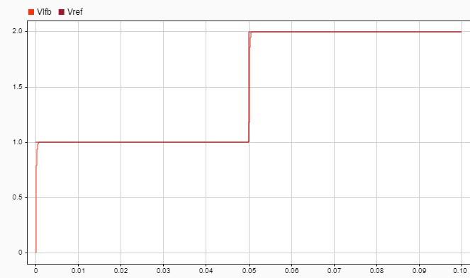
Run the simulation. The Simulation Data Inspector shows the simulation of the reference voltage step that the first C2000 processor requests from the second processor. The result shows that the step request occurs at 0.05 s and the output of the converter, marked Vfb on the figure, tracks the set point, marked Vref.

Deployment
After you deploy the DC-DC power converter to a product, you must perform tuning and logging at the deployment site. Doing so requires accessing the device only through the SCI, as Simulink with external mode might not be available to the end user.
Target Model
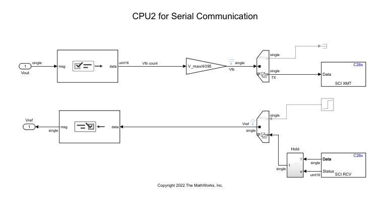
The model, when deployed to the hardware board uses the Variant Source and Variant Sink blocks to read and write to the C28x SCI Receive and C28x SCI Transmit blocks, respectively. This figure shows the model configured for deployment.

Connection to Host
This section shows a sample serial connection from MATLAB to the deployed model running on the C2000 hardware board. The communication samples the measured voltage from the hardware and commands a change in voltage from 1 V to 2 V.
serial = serialport("COM8",115200,"Timeout",5);
serial.flush;

write(serial,1,"single");
data = read(serial,32,"single");

write(serial,2,"single");
data = [data,read(serial,32,"single")];

plot(data);
xlabel('Sample');
ylabel('Measured Voltage [Volts]');
write(serial,1,"single");

The figure shows that the measured voltage matches the expected voltage and that the deployed C2000 hardware board reacts to the specified command only using the information transmitted by the serial connection. In this configuration, the output voltage can be measured and controlled using only a serial connection.
Further Exploration
Connect to the deployed model from development computer using other languages and libraries, such as Python, JavaScript®, or C/C++.
Modify the model to buffer the serial data prior to transmission for more efficient data throughput.