Main Content

crcConfig

Cyclic redundancy check (CRC) coding configuration

Since R2024a

Description

crcCfg = crcConfig returns the crcCfg object with the default CRC configuration. Use the default configuration object for generation of 16-bit CRC or detection of errors in input data. For more information, see Algorithms.

example

crcCfg = crcConfig(Name=Value) returns the crcCfg object configured as specified by one or more name-value arguments. For example, crcCfg = crcConfig(Polynomial='z^3 + 1',ChecksumsPerFrame=2) returns a CRC configuration object that assigns the p(z) = z3 + 1 generator polynomial and two checksums per frame.

Examples

collapse all

Show CRC using the indirect algorithm for the input frame [1 1 0 0 1 1 0]', corresponding to the polynomial M=x6+x5+x2+x.

Generate an input frame that corresponds to the polynomial M=x6+x5+x2+x.

x = logical([1 1 0 0 1 1 0]');

Configure a crcConfig object with the degree r = 3 generator polynomial P=x3+x2+1 and display the object.

gp = 'x^3 + x^2 + 1';
crcCfg = crcConfig(Polynomial=gp)
crcCfg = 
  crcConfig with properties:

           Polynomial: 'x^3 + x^2 + 1'
    InitialConditions: 0
         DirectMethod: 0
    ReflectInputBytes: 0
     ReflectChecksums: 0
             FinalXOR: 0
    ChecksumsPerFrame: 1

Generate the CRC. By polynomial division, M×x3=x9+x8+x5+x4=(x6+x3+x)×P+x. The remainder is x, so that the checksum is then [0 1 0]'. An extra 0 is added on the left to make the checksum have length 3. The output codeword has the checksum appended at the end of the input frame.

codeword = crcGenerate(x,crcCfg)
codeword = 10x1 logical array

   1
   1
   0
   0
   1
   1
   0
   0
   1
   0

Comparing the last three bits to the expected checksum we see they match.

isequal([0 1 0]', codeword(8:end))
ans = logical
   1

Add a CRC checksum to the transmission and reception of multichannel input data frames.

Configure a crcConfig object with the degree r = 4 generator polynomial P=x4+x3+x2+x+1 and display the object.

gp = 'z^4 + z^3 + z^2 + z + 1';
crcobj = crcConfig(Polynomial='z^4 + z^3 + z^2 + z + 1')
crcobj = 
  crcConfig with properties:

           Polynomial: 'z^4 + z^3 + z^2 + z + 1'
    InitialConditions: 0
         DirectMethod: 0
    ReflectInputBytes: 0
     ReflectChecksums: 0
             FinalXOR: 0
    ChecksumsPerFrame: 1

Generate an multichannel input frames of logical data. Generate CRC checksum for each frame and append checksum to each frame in each channel of the signal to be transmitted by using the crcGenerate function.

x = logical(randsrc(10,3,[0,1]));
cw = crcGenerate(x,crcobj);

Filter the first channel through a binary symmetric channel with a 20% probability of error. Identify indices of bits in error by using the find function. Detect errors in the received multichannel input frames of logical data by using the crcDetect function.

cwrx = [bsc(cw(:,1),0.2), cw(:,2), cw(:,3)];
(find(cw-cwrx))'
ans = 1×4

     2     4     5    10

[tx,err] = crcDetect(cwrx,crcobj);
err
err = 1x3 logical array

   1   0   0

Generate two message words of length 6.

x = logical([1 0 1 1 0 1 0 1 1 1 0 1]');

Encode the message words using a 3-bit CRC generator.

cfgObj = crcConfig(Polynomial='z^3 + 1',ChecksumsPerFrame=2);
codeword = crcGenerate(x,cfgObj);

Add one bit error to each codeword.

errorPattern = randerr(2,9,1).';
codewordWithError = xor(codeword,errorPattern(:));

Decode messages with and without errors. The crcDetect function reports no errors in the transmitted message words for codeword and reports errors in both transmitted message words for codewordWithError.

[tx,err] = crcDetect(codeword,cfgObj);
[tx1,err1] = crcDetect(codewordWithError,cfgObj);
disp(err)
   0
   0
disp(err1)
   1
   1

Input Arguments

collapse all

Name-Value Arguments

Specify optional pairs of arguments as Name1=Value1,...,NameN=ValueN, where Name is the argument name and Value is the corresponding value. Name-value arguments must appear after other arguments, but the order of the pairs does not matter.

Example: crcCfg = crcConfig(Polynomial='z^3 + 1',ChecksumsPerFrame=2)

Generator polynomial for the CRC algorithm, specified as one of these options:

  • Character vector or string scalar of a polynomial whose constant term is 1. For more information, see Representation of Polynomials in Communications Toolbox.

  • Binary-valued row vector that represents the coefficients of the polynomial in degree of descending powers. The length of this vector must be (P + 1), where P is the degree of the polynomial. The first and last entries must be 1, indicating the leading term with degree P and a constant term of 1.

  • Integer-valued row vector of elements that represent the exponents for the nonzero terms of the polynomial in degree of descending powers. The last entry must be 0, indicating a constant term of 1.

The default value is the CRC-16-CCITT generator polynomial. This table lists some commonly used generator polynomials.

CRC NameGenerator Polynomial
CRC-32'z^32 + z^26 + z^23 + z^22 + z^16 + z^12 + z^11 + z^10 + z^8 + z^7 + z^5 + z^4 + z^2 + z + 1'
CRC-24 'z^24 + z^23 + z^14 + z^12 + z^8 + 1'
CRC-16 'z^16 + z^15 + z^2 + 1'
CRC-16-CCITT'z^16 + z^12 + z^5 + 1'
Reversed CRC-16'z^16 + z^14 + z + 1'
CRC-8'z^8 + z^7 + z^6 + z^4 + z^2 + 1'
CRC-4 'z^4 + z^3 + z^2 + z + 1'

Example: 'z^16 + z^12 + z^5 + 1', '0x10811', [1 0 0 0 1 0 0 0 0 0 0 1 0 0 0 0 1], and [16 12 5 0] represent the same polynomial, p(z) = z16 + z12 + z5 + 1.

Data Types: double | char | string

Initial states of shift register, specified as a binary scalar or vector.

  • When you specify initial conditions as a vector, the length must equal the degree of the generator polynomial that you specify in the Polynomial property.

  • When you specify initial conditions as a scalar, vector expansion repeats the value to a column vector with a length equal to the degree of the generator polynomial.

Data Types: logical

Use the direct algorithm for CRC checksum calculations, specified as a numeric or logical 0 (false) or 1 (true). Set this property to true to use the direct algorithm. To learn about direct and nondirect algorithms, see Direct and Indirect CRC Algorithm.

Data Types: logical

Reflect input bytes, specified as a numeric or logical 0 (false) or 1 (true). Set this property to true to flip the input data on a byte-wise basis before the data enters the shift register. When you set this property to true:

  • For the crcGenerate function, the input frame length divided by the ChecksumsPerFrame property value must be an integer multiple of 8.

  • For the crcDetect function, the input frame length divided by the ChecksumsPerFrame property value minus the degree of the generator polynomial, which you specify in the Polynomial property, N/CP bits must be an integer multiple of 8. N is the column length of the input frame, C is the number of checksums per frame (ChecksumsPerFrame) and P is the degree of the generator polynomial (Polynomial).

Data Types: logical

Reflect checksums before final XOR, specified as a numeric or logical 0 (false) or 1 (true). Set this property to true to flip the CRC checksums around their centers before the final XOR.

Data Types: logical

Final XOR value, specified as a binary scalar or vector. The XOR operation runs using the value of the FinalXOR property. The crcGenerate function applies the XOR operation to the computed CRC bits before appending them to the input frame. The crcDetect function applies the XOR operation to computed CRC bits before comparing with the input checksum.

  • When specified as a vector, the length must equal the degree of the generator polynomial that you specify in the Polynomial property.

  • When specified as a scalar, vector expansion repeats the value to a column vector with a length equal to the degree of the generator polynomial.

Data Types: logical

Number of checksums calculated for each input frame, specified as a positive integer. For more information, see Algorithms.

Data Types: double

Output Arguments

collapse all

CRC configuration object, returned as a crcConfig object.

Algorithms

collapse all

Cyclic Redundancy Check Coding

Cyclic redundancy check (CRC) coding is an error-control coding technique for detecting errors that occur when transmitting a data frame. Unlike block or convolutional codes, CRC codes do not have a built-in error-correction capability. Instead, when a communications system detects a CRC coding error in a received codeword, the receiver requests the sender to retransmit the codeword.

In CRC coding, the transmitter applies a rule to each data frame to create extra CRC bits, called the checksum or syndrome, and then appends the checksum to the data frame. After receiving a transmitted codeword, the receiver applies the same rule to the received codeword. if the resulting checksum is nonzero, an error has occurred and the transmitter should resend the data frame.

When the number of checksums per frame is greater than 1, the input data frame is divided into subframes, the rule is applied to each data subframe, and individual checksums are appended to each subframe. The subframe codewords are concatenated to output one frame. For features that support matrix inputs, each column of input data is processed independently.

To ensure matching CRC configurations, use the same crcConfig object for the crcGenerate and crcDetect functions. For more information about the checksums see CRC Generator Operation and CRC Syndrome Detector Operation on the crcGenerate and crcDetect function reference pages, respectively.

Direct and Indirect CRC Algorithm

The crcConfig function supports generation and detection of CRC checksum by using the indirect or direct CRC algorithm.

Indirect CRC Algorithm

The indirect CRC algorithm accepts a binary data vector, corresponding to a polynomial M, and appends a checksum of r bits, corresponding to a polynomial C. The concatenation of the input vector and the checksum then corresponds to the polynomial T = M×xr + C, since multiplying by xr corresponds to shifting the input vector r bits to the left. The algorithm chooses the checksum C so that T is divisible by a predefined polynomial P of degree r, called the generator polynomial.

The algorithm divides T by P, and sets the checksum equal to the binary vector corresponding to the remainder. That is, if T = Q×P + R, where R is a polynomial of degree less than r, the checksum is the binary vector corresponding to R. If necessary, the algorithm prepends zeros to the checksum so that it has length r.

The CRC generation feature, which implements the transmission phase of the CRC algorithm, does the following:

  1. Left shifts the input data vector by r bits and divides the corresponding polynomial by P.

  2. Sets the checksum equal to the binary vector of length r, corresponding to the remainder from step 1.

  3. Appends the checksum to the input data vector. The result is the output vector.

The CRC detection feature computes the checksum for its entire input vector, as described above.

The CRC algorithm uses binary vectors to represent binary polynomials, in descending order of powers. For example, the vector [1 1 0 1] represents the polynomial x3 + x2 + 1.

Block diagram for indirect CRC algorithm

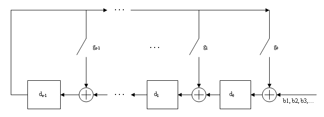
Bits enter the linear feedback shift register (LFSR) from the lowest index bit to the highest index bit. The sequence of input message bits represents the coefficients of a message polynomial in order of decreasing powers. The message vector is augmented with r zeros to flush out the LFSR, where r is the degree of the generator polynomial. If the output from the leftmost register stage d(1) is a 1, then the bits in the shift register are XORed with the coefficients of the generator polynomial. When the augmented message sequence is completely sent through the LFSR, the register contains the checksum [d(1) d(2) . . . d(r)]. This is an implementation of binary long division, in which the message sequence is the divisor (numerator) and the polynomial is the dividend (denominator). The CRC checksum is the remainder of the division operation.

Direct CRC Algorithm

This block diagram shows the direct CRC algorithm.
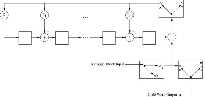
Block diagram for the direct CRC algorithm

Where Message Block Input is m0,m1,...,mk1 and Code Word Output is

c0,c1,...,cn1=m0,m1,...,mk1,Xd0,d1,...,dnk1Y

The initial step of the direct CRC encoding occurs with the three switches in position X. The algorithm feeds k message bits to the encoder. These bits are the first k bits of the code word output. Simultaneously, the algorithm sends k bits to the linear feedback shift register (LFSR). When the system completely feeds the kth message bit to the LFSR, the switches move to position Y. Here, the LFSR contains the mathematical remainder from the polynomial division. These bits are shifted out of the LFSR and they are the remaining bits (checksum) of the code word output.

References

[1] Sklar, Bernard. Digital Communications: Fundamentals and Applications. Englewood Cliffs, NJ: Prentice-Hall, 1988.

[2] Wicker, Stephen B., Error Control Systems for Digital Communication and Storage. Upper Saddle River, NJ, Prentice Hall, 1995.

Extended Capabilities

C/C++ Code Generation
Generate C and C++ code using MATLAB® Coder™.

Version History

Introduced in R2024a