Analyzing Spacecraft Attitude Profiles with Satellite Scenario
This example shows how to propagate the orbit and attitude states of a satellite in Simulink® and visualize the computed trajectory and attitude profile in a satellite scenario. It uses:
Aerospace Blockset™ Spacecraft Dynamics block
Aerospace Blockset Attitude Profile block
Aerospace Toolbox
satelliteScenarioobject
The Spacecraft Dynamics block models translational and rotational dynamics of spacecraft using numerical integration. It computes the position, velocity, attitude, and angular velocity of one or more spacecraft over time. For the most accurate results, use a variable step solver with low tolerance settings (less than 1e-8). Depending on your mission requirements, you can increase speed by using larger tolerances. Doing so might impact the accuracy of the solution.
The Attitude Profile block returns the shortest quaternion rotation that aligns the satellite's provided alignment axis with the specified target. In this example, the satellite points towards the nadir at the beginning of the mission, then slews to align with Target 1, points back at the nadir, then slews to point at Target 2. Both targets are provided as geographic locations.
The Aerospace Toolbox satelliteScenario object lets you load previously generated, time-stamped ephemeris and attitude data into a scenario as timeseries or timetable objects. Data is interpolated in the scenario object to align with the scenario time steps, allowing you to incorporate data generated in a Simulink model into either a new or existing satelliteScenario object. In this example, the satellite orbit and attitude states are computed with the Spacecraft Dynamics block, then this data is used to add a satellite to a new satelliteScenario object for access analysis.
Open the Example Model
The example model is configured to perform an Earth Observation mission during which a satellite performs a flyover of a region of the Amazon Rainforest to capture images of, and track deforestation trends in, the area. The satellite points at the nadir when not actively imaging or downlinking to the ground station in Svalbard, NO.
mission.mdl = "SpacecraftDynamicsCustomAttitudeExampleModel";
open_system(mission.mdl);
Define Mission Parameters and Satellite Initial Conditions
Specify a start date and duration for the mission. This example uses MATLAB® structures to organize mission data. These structures make accessing data later in the example more intuitive. They also help declutter the global base workspace.
mission.StartDate = datetime(2021,1,1,12,0,0);
mission.Duration = hours(1.5);
Set Satellite Properties on Spacecraft Dynamics Block
Specify initial orbital elements for the satellite.
mission.Satellite.blk = mission.mdl + "/Spacecraft Dynamics";
mission.Satellite.SemiMajorAxis  = 7.2e6; % meters
mission.Satellite.Eccentricity   = .05;
mission.Satellite.Inclination    = 70;    % deg
mission.Satellite.ArgOfPeriapsis = 0;     % deg
mission.Satellite.RAAN           = 215;   % deg
mission.Satellite.TrueAnomaly    = 200;   % deg
Specify an initial attitude state for the satellite.
mission.Satellite.q0 = [0.1509 0.4868 0.3031 -0.8052];
mission.Satellite.pqr = [0, 0, 0]; % deg/s
Configure the Spacecraft Dynamics block with the provided initial conditions and desired propagation settings. These values can also be set from the Property Inspector in Simulink.
set_param(mission.Satellite.blk, ...
    "startDate",      string(juliandate(mission.StartDate)), ...
    "stateFormatNum", "Orbital elements", ...
    "orbitType",      "Keplerian", ...
    "semiMajorAxis",  string(mission.Satellite.SemiMajorAxis), ...
    "eccentricity",   string(mission.Satellite.Eccentricity), ...
    "inclination",    string(mission.Satellite.Inclination), ...
    "raan",           string(mission.Satellite.RAAN), ...
    "argPeriapsis",   string(mission.Satellite.ArgOfPeriapsis), ...
    "trueAnomaly",    string(mission.Satellite.TrueAnomaly));
set_param(mission.Satellite.blk, ...
    "attitudeFormat", "Quaternion", ...
    "attitudeFrame",  "ICRF", ...
    "attitude",       mat2str(mission.Satellite.q0), ...
    "attitudeRate",   mat2str(mission.Satellite.pqr));
Use the EGM2008 spherical harmonic gravity model for orbit propagation.
set_param(mission.Satellite.blk, ...
    "gravityModel", "Spherical Harmonics", ...
    "earthSH",      "EGM2008", ... % Earth spherical harmonic potential model
    "shDegree",     "120", ... % Spherical harmonic model degree and order
    "useEOPs",      "on", ... % Use EOP's in ECI to ECEF transformations
    "eopFile",      "aeroiersdata.mat"); % EOP data file
Gravity gradient torque contributions can be included in attitude dynamics calculations.
set_param(mission.Satellite.blk, "useGravGrad", "on");
Configure Attitude Profile Block for Target Pointing
The Attitude Profile block targets two ground locations, first a location in the Amazon Rainforest of Brazil for observation of deforestation, and second for down-linking image data to a ground station in Svalbard, NO. The block is preconfigured in the model as shown below.
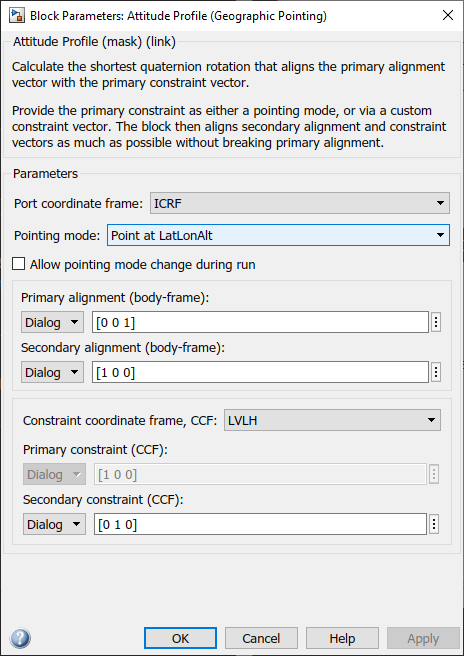
The "Point at LatLonAlt" option is selected for the Pointing mode parameter. The z-axis is used as the satellite's primary alignment vector. This means that the satellite Body z-axis points towards the geographic coordinates passed into the block throughout the simulation. The y-Axis of the LVLH frame, which points along-track in the direction of travel, is defined as the secondary constraint vector. The satellite Body x-axis is specified as the secondary alignment vector. This keeps our satellite pointed forward throughout the mission as much as possible without disrupting primary alignment.
Set Up Simulink Model to Produce Desired Output
Apply model-level solver setting using set_param. For best performance and accuracy, use a variable-step solver. Set the max step size to a value that results in output data without large time gaps.
set_param(mission.mdl, ...
    "SolverType", "Variable-step", ...
    "SolverName", "VariableStepAuto", ...
    "RelTol",     "0.5e-5", ...
    "AbsTol",     "1e-5", ...
    "MaxStep",    "5", ...
    "MinStep",    "auto", ...
    "StopTime",   string(seconds(mission.Duration)));
Save model output port data as a dataset of timetable objects.
set_param(mission.mdl, ...
    "SaveOutput", "on", ...
    "OutputSaveName", "yout", ...
    "SaveFormat", "Dataset", ...
    "DatasetSignalFormat", "timetable");
Run the Model and Collect Satellite Ephemeris and Attitude Profile
Simulate the model. In this example, the Spacecraft Dynamics block outputs position and velocity states in the inertial (ICRF/GCRF) coordinate frame.
mission.SimOutput = sim(mission.mdl);
Create and Visualize the Satellite Scenario
For the analysis, create a satellite scenario object. Specify a timestep of 1 minute.
scenario = satelliteScenario(mission.StartDate, ...
    mission.StartDate + mission.Duration, 60);
Add the two targets as ground stations in Brazil and Svalbard.
gsNO = groundStation(scenario, 78, 21, Name="Svalbard, NO")gsNO =
GroundStation with properties:
Name: Svalbard, NO
ID: 1
Latitude: 78 degrees
Longitude: 21 degrees
Altitude: 0 meters
MinElevationAngle: 0 degrees
ConicalSensors: [1x0 matlabshared.satellitescenario.ConicalSensor]
Gimbals: [1x0 matlabshared.satellitescenario.Gimbal]
Transmitters: [1x0 satcom.satellitescenario.Transmitter]
Receivers: [1x0 satcom.satellitescenario.Receiver]
Accesses: [1x0 matlabshared.satellitescenario.Access]
Eclipse: [1x0 Aero.satellitescenario.Eclipse]
CoordinateAxes: [1x1 matlabshared.satellitescenario.CoordinateAxes]
MarkerColor: [1 0.4118 0.1608]
MarkerSize: 6
ShowLabel: true
LabelFontColor: [1 1 1]
LabelFontSize: 15
gsAmazon = groundStation(scenario, -4.9, -66, Name="Amazon Rainforest")gsAmazon =
GroundStation with properties:
Name: Amazon Rainforest
ID: 2
Latitude: -4.9 degrees
Longitude: -66 degrees
Altitude: 0 meters
MinElevationAngle: 0 degrees
ConicalSensors: [1x0 matlabshared.satellitescenario.ConicalSensor]
Gimbals: [1x0 matlabshared.satellitescenario.Gimbal]
Transmitters: [1x0 satcom.satellitescenario.Transmitter]
Receivers: [1x0 satcom.satellitescenario.Receiver]
Accesses: [1x0 matlabshared.satellitescenario.Access]
Eclipse: [1x0 Aero.satellitescenario.Eclipse]
CoordinateAxes: [1x1 matlabshared.satellitescenario.CoordinateAxes]
MarkerColor: [1 0.4118 0.1608]
MarkerSize: 6
ShowLabel: true
LabelFontColor: [1 1 1]
LabelFontSize: 15
Add the observation satellite to the scenario. Update the position timetable data in the SimOutput object to remove excess data points.
mission.Satellite.Ephemeris = retime(mission.SimOutput.yout{1}.Values, ...
    seconds(uniquetol(mission.SimOutput.tout, .0001)));
sat = satellite(scenario, mission.Satellite.Ephemeris, ...
    "CoordinateFrame", "inertial", "Name", "ObservationSat");
Add a conical sensor to the satellite, with a 35 deg half angle to represent the onboard camera. Enable field of view visualization in the scenario viewer. To assist in visualization, the sensor is mounted 10m from the satellite, in the +z direction.
snsr = conicalSensor(sat, MaxViewAngle=70, MountingLocation=[0 0 10]);
fieldOfView(snsr);
Add access between the conical sensor and the two ground stations.
acNO = access(snsr, gsNO)
acNO =
  Access with properties:

    Sequence:  [4 1]
    LineWidth:  3
    LineColor:  [0.3922 0.8314 0.0745]
acAmazon = access(snsr, gsAmazon)
acAmazon =
  Access with properties:

    Sequence:  [4 2]
    LineWidth:  3
    LineColor:  [0.3922 0.8314 0.0745]
Use the pointAt method to associate the logged attitude timetable with the satellite. Parameter ExtrapolationMethod controls the pointing behavior outside of the timetable range.
mission.Satellite.AttitudeProfile = retime(mission.SimOutput.yout{3}.Values, ...
    seconds(uniquetol(mission.SimOutput.tout, .0001)));
pointAt(sat, mission.Satellite.AttitudeProfile, ...
    "CoordinateFrame", "inertial", "Format", "quaternion", "ExtrapolationMethod", "nadir");
Open the Satellite Scenario Viewer to view and interact with the scenario.
viewer1 = satelliteScenarioViewer(scenario);
Assign a 3-D model to the satellite and visualize its coordinate axes. The red, green and blue arrows point along the x, y and z axes of the body frame of the satellite.
sat.Visual3DModel = "SmallSat.glb";
coordinateAxes(sat, Scale=2);
camtarget(viewer1, sat);
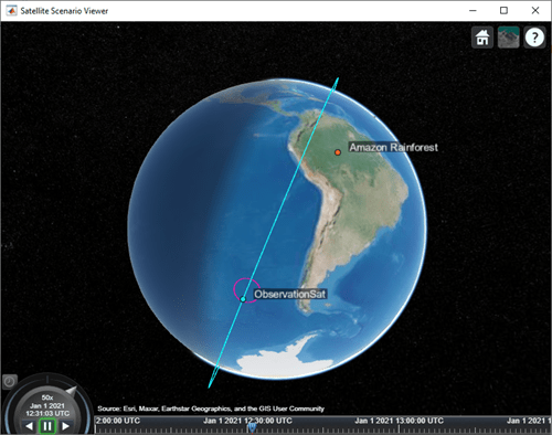
The satellite points at the nadir to begin the scenario. The magenta marker represents the conical sensor.
As the satellite nears Target 1 in the Amazon Rainforest, it slews to point and track this target.
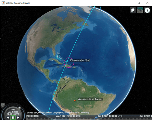
After the imaging segment is complete, the satellite returns to pointing at the nadir.
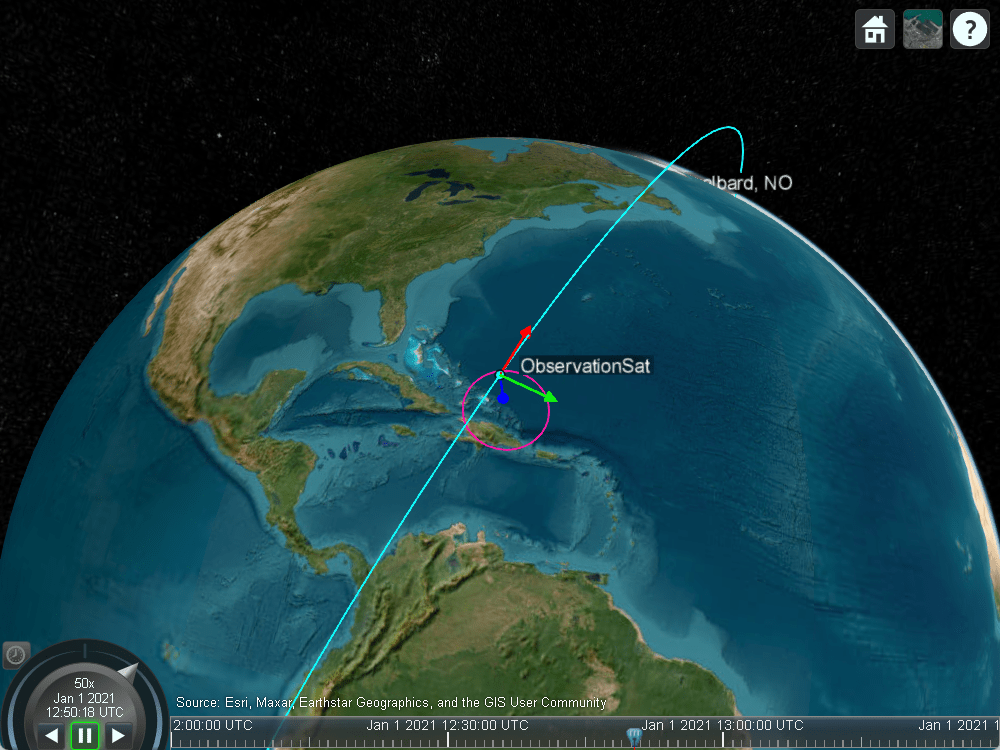
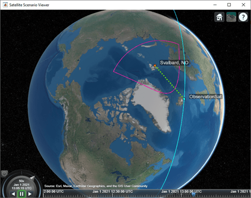
As the satellite comes into range of the arctic ground station, it slews to point at this target.


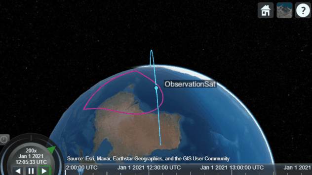
Custom Gimbal Steering
This example shows how to import custom attitude data for a simple Earth Observation satellite mission in MATLAB and Simulink, where the onboard camera is fixed to the satellite body. Another common approach is to fix the sensor on a gimbal and orient the sensor by maneuvering the gimbal, rather than the spacecraft body itself. Modify the above scenario to mount the sensor on a gimbal and steer the gimbal to perform uniform sweeps of the area directly below the satellite.
Reset the satellite to always point at nadir, overwriting the previously provided custom attitude profile.
delete(viewer1);
pointAt(sat, "nadir");
Delete the existing sensor object to remove it from the satellite and attach a new sensor with the same properties to a gimbal.
delete(snsr);
gim = gimbal(sat);
snsr = conicalSensor(gim, MaxViewAngle=70, MountingLocation=[0 0 10]);
fieldOfView(snsr);
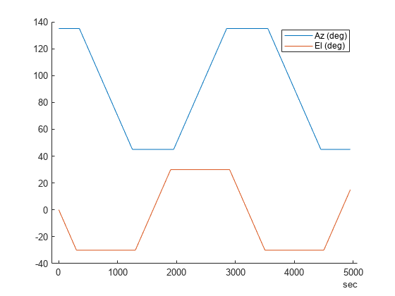
Define azimuth and elevation angles for gimbal steering to model a sweeping pattern over time below the satellite.
gimbalSweep.Time = seconds(1:50:5000)';

gimbalSweep.Az = [...
    45*ones(1,7),...
    45:-5:-45,...
    -45*ones(1,13),...
    -45:5:45,...
    45*ones(1,13),...
    45:-5:-45,...
    -45*ones(1,13)];
gimbalSweep.Az(end-2:end) = [];
gimbalSweep.Az = gimbalSweep.Az + 90;

gimbalSweep.El = [...
    0:-5:-30,...
    -30*ones(1,19),...
    -30:5:30,...
    30*ones(1,19),...
    30:-5:-30,...
    -30*ones(1,19),...
    -30:5:30];
gimbalSweep.El(end-2:end) = [];
Plot the commanded azimuth and elevation values over time.
figure(1)
hold on;
plot(gimbalSweep.Time', gimbalSweep.Az);
plot(gimbalSweep.Time', gimbalSweep.El);
hold off;
legend(["Az (deg)", "El (deg)"]);
Store the azimuth and elevation angles in a timetable.
gimbalSweep.TT = timetable(gimbalSweep.Time, [gimbalSweep.Az', gimbalSweep.El']);
Steer the gimbal with the timetable. The gimbal returns to its default orientation for timesteps that are outside of the provided data.
pointAt(gim, gimbalSweep.TT);
View the updated scenario in the Satellite Scenario Viewer.
viewer2 = satelliteScenarioViewer(scenario);
See Also
Blocks
Objects
Select a Web Site
Choose a web site to get translated content where available and see local events and offers. Based on your location, we recommend that you select: United States.
You can also select a web site from the following list
Americas
- América Latina (Español)
- Canada (English)
- United States (English)
Europe
- Belgium (English)
- Denmark (English)
- Deutschland (Deutsch)
- España (Español)
- Finland (English)
- France (Français)
- Ireland (English)
- Italia (Italiano)
- Luxembourg (English)
- Netherlands (English)
- Norway (English)
- Österreich (Deutsch)
- Portugal (English)
- Sweden (English)
- Switzerland
- United Kingdom (English)
Asia Pacific
- Australia (English)
- India (English)
- New Zealand (English)
- 中国
- 日本Japanese (日本語)
- 한국Korean (한국어)