End-to-End Bluetooth LE PHY Simulation with Multipath Fading Channel, RF Impairments, and Corrections
This example shows an end-to-end simulation to measure the bit error rate (BER) and packet error rate (PER) for different Bluetooth® low energy (LE) physical layer (PHY) packet types by using Bluetooth® Toolbox. The PHY packet types are distorted by adding the radio frequency (RF) impairments, multipath fading channel, and additive white Gaussian noise (AWGN). The simulation results show the BER and PER values for each PHY mode with different fading channel models.
RF Impairments and Multipath Fading Channel Models
Bluetooth Special Interest Group (SIG) [1] introduced Bluetooth LE for low-power short-range communications. Bluetooth LE devices operate in the globally unlicensed industrial, scientific, and medical (ISM) band in the frequency range of 2.4 GHz to 2.485 GHz. Bluetooth LE specifies a channel spacing of 2 MHz, which results in 40 RF channels. The Bluetooth LE standard specifies the link layer (LL) which includes both PHY and MAC layers. Bluetooth LE applications include image and video file transfers between mobile phones, home automation, and the Internet of Things (IoT). Bluetooth LE supports these PHY transmission modes.
Uncoded PHY with a data rate of 1 Mbps (LE1M)
Uncoded PHY with a data rate of 2 Mbps (LE2M)
Coded PHY with a data rate of 500 Kbps (LE500K)
Coded PHY with a data rate of 125 Kbps (LE125K)
RF Impairments
In this example, each Bluetooth LE packet is distorted with these RF impairments.
DC offset
Carrier frequency offset
Carrier phase offset
Timing drift
Phase noise
Fading channel model
Channel Model
The example supports these channel models.
Rayleigh and Rician Channel Models
Rayleigh and Rician fading channels are useful models of real-world phenomena in wireless communication. These channel models include multipath scattering effects, time dispersion, and Doppler shifts that arise from relative motion between the transmitter and receiver. This figure shows direct and major reflected paths between a stationary radio transmitter and a stationary radio receiver. The shaded shapes represent the reflecting surfaces such as walls.
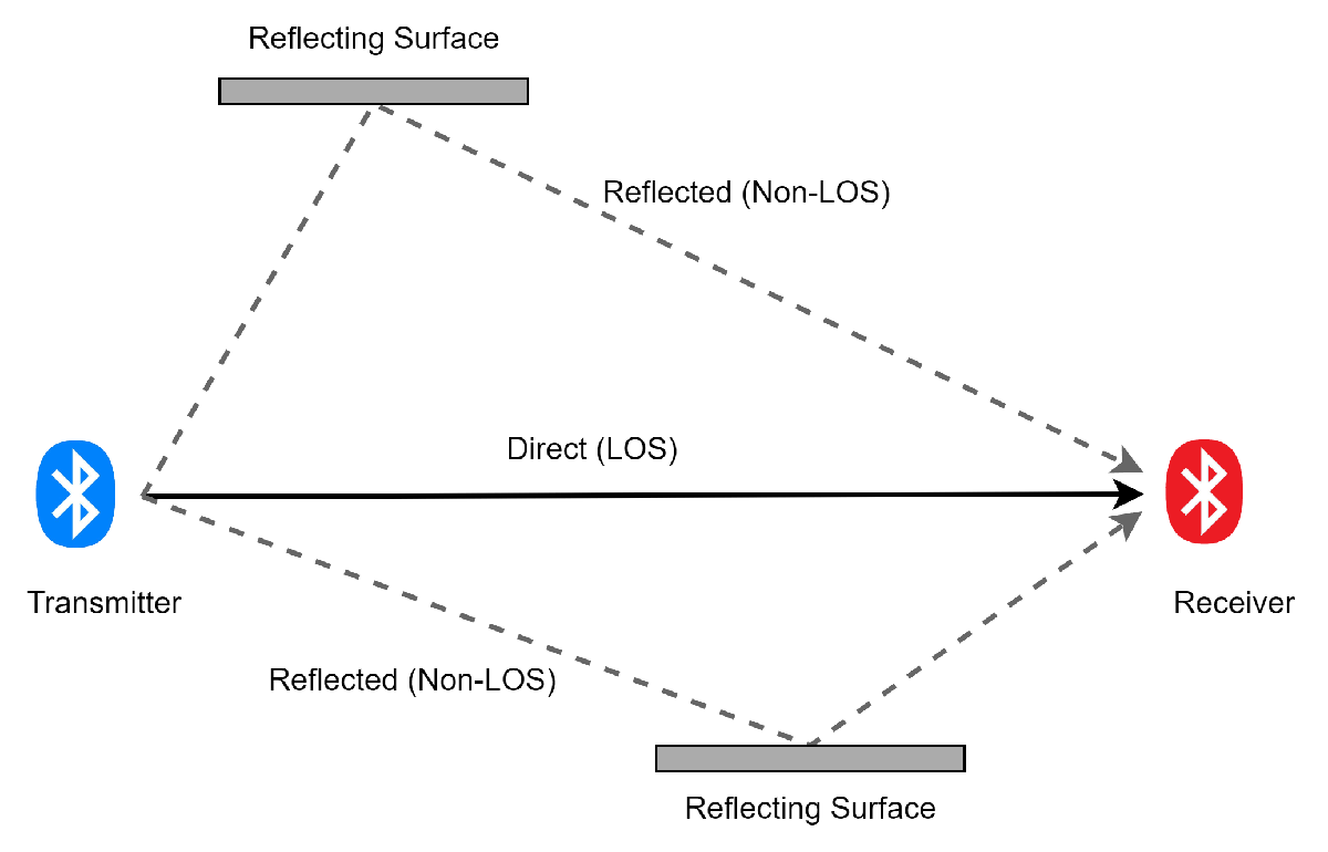
The reflected paths non-line of sight (NLOS) result in the arrival of delayed versions of the signal at the receiver. In addition, the radio signal undergoes scattering on a local scale for each major path. Such local scattering typically results from reflections of objects near the receiver. These irresolvable components combine at the receiver and cause a phenomenon known as multipath fading. Due to this phenomenon, each major path behaves as a discrete fading path. Typically, the fading process is characterized by a Rayleigh distribution for an NLOS path and a Rician distribution for a LOS path.
For more information about how to use Rayleigh and Rician channel models, see Fading Channels.
Raytracing Channel Model
This channel model uses raytracing in an indoor environment between one transmitter site and one receiver site in a 3-D conference room. The channel model uses computed rays to construct a deterministic channel model specific to the Bluetooth LE Tx-Rx communication link. The same raytracing methods can be applied to build channel models for indoor and outdoor environments.
For more information about how to implement a raytracing channel model in an outdoor environment, see Urban Link and Coverage Analysis Using Ray Tracing.
End-to-End Simulation Workflow
This figure shows the workflow of this end-to-end simulation. After you add the RF impairments, the Bluetooth LE waveforms are distorted with the fading channel model and AWGN. The noisy waveform is then received at the practical receiver.
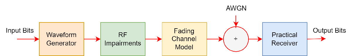
This figure shows the operational workflow of the practical receiver.
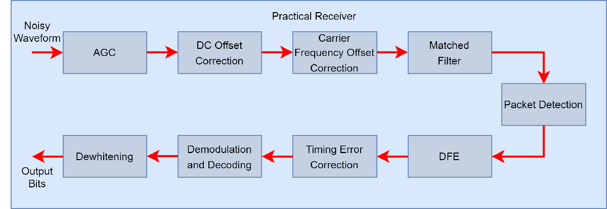
The practical receiver receives the noisy waveforms as input and performs these operations.
Automatic gain control (AGC)
DC removal
Carrier frequency offset correction
Matched filtering
Packet detection
Decision feedback equalization (DFE)
Timing error correction
Demodulation and decoding
De-whitening
Simulations
Configuration
Specify the noise power spectral density (Eb/No), samples per symbol, data length, and PHY transmission modes.
EbNo = 2:4:24; % Eb/No in dB sps = 4; % Samples per symbol, must be greater than 1 dataLength =128; % Data length in bytes, includes a header, a payload and a cycle redundancy check (CRC) simMode = ["LE1M","LE2M","LE500K","LE125K"]; % PHY transmission modes
Specify the type of fading channel model as "AWGN", "Rician Channel", "Rayleigh Channel", or "Raytracing Channel".
channelModel =  "Raytracing Channel" ;
Enable or disable the DFE by checking the enableEqualizer flag. Enabling DFE will mitigate the effects of the fading channel model on the Bluetooth LE transmit waveforms.
enableEqualizer =  false;
Enable or disable the AGC by checking the enalbeAGC flag. Enabling the AGC will mitigate the effects of path loss on the Bluetooth LE transmit waveforms.
enableAGC =  true;
true;These parameters control the number of packets tested at each Eb/No point.
maxNumErrors: This parameter specifies the maximum number of bit errors simulated at each Eb/No point. When the number of bit errors reaches this value, the simulation at this Eb/No is complete.maxNumPackets: This parameter specifies the maximum number of packets simulated at each Eb/No point. When the number of packets reaches this value, the simulation at this Eb/No is complete.
Specify the maxNumErrors and maxNumPackets values. For the purpose of this example, specify small values for maxNumErrors and maxNumPackets. For statistically meaningful results, you can simulate the example with higher maxNumErrors and maxNumPackets values.
maxNumErrors = 10;
maxNumPackets = 100;
Get the number of PHY modes for simulation.
numMode = numel(simMode);
Calculate the number of Eb/No points of simulation.
snrLength = length(EbNo);
Preallocate the space to store the BER and PER results.
[ber,per] = deal(zeros(numMode,snrLength));
If you specify the channel model as "Raytracing Channel", preallocate the space to store data for the site viewer.
if channelModel=="Raytracing Channel"
    visualVar = cell(numMode,snrLength);
end
Specify the number of bits per byte.
bitsPerByte = 8;
Simulate for Each PHY mode
This example demonstrates how to speed up the simulation by using a parfor loop, instead of a for loop simulate each Eb/No point. The parfor loop reduces the total simulation time by executing the processing for each PHY mode simultaneously. To utilize the parfor loop, you need the Parallel Computing Toolbox™ license. By commenting out the for statement, you can enable the use of parallel computing and enhance simulation speed. If you do not install the Parallel Computing Toolbox , by default, the example uses the for loop causing the simulation to run on a single core.
% parfor countMode = 1:numMode
for countMode = 1:numMode
For each PHY mode, set the signal-to-noise ratio (SNR). For coded PHYs (LE500K and LE125K), the SNR calculation includes the 1/2 and 1/8 code rate respectively.
    phyMode = simMode(countMode);

    if any(phyMode==["LE1M","LE2M"])
        snrVec = EbNo - 10*log10(sps);
    else
        if phyMode == "LE500K"
            codeRate = 1/2;
        else
            codeRate = 1/8;
        end
        snrVec = EbNo + 10*log10(codeRate) - 10*log10(sps);
    end
Calculate the sampling frequency of the generated waveform.
sampleRate = sps*(1+(phyMode=="LE2M"))*1e6;Simulate for Each Eb/No Point
for countSnr = 1:snrLengthTo ensure that each iteration uses a repeatable set of random numbers, set a random substream index for each iteration.
        stream = RandStream("combRecursive");
        stream.Substream = countSnr;
        RandStream.setGlobalStream(stream);
Create an instance of error rate.
        errorRate = comm.ErrorRate(Samples="Custom", ...
            CustomSamples=1:(dataLength*bitsPerByte-1));
To configure the RF impairments, use the helperBLEImpairmentsInit helper object.
initImp = helperBLEImpairmentsInit(phyMode,sps);
Initialize and update the fading channel model.
        channelInit = cell(1,1);
        if channelModel~="AWGN"
            channelInit = helperBluetoothChannelInit(sampleRate,channelModel);
        end
Configure the parameters of the practical receiver.
        rxCfg = struct(Mode=phyMode,SamplesPerSymbol=sps, ...
            DFPacketType="Disabled");
        rxCfg.CoarseFreqCompensator = comm.CoarseFrequencyCompensator(Modulation="OQPSK", ...
            SampleRate=sampleRate, ...
            SamplesPerSymbol=2*sps, ...
            FrequencyResolution=30);
        rxCfg.PreambleDetector = comm.PreambleDetector(Detections="First");
Initialize the parameters for error computation. The numErrors is used for accumulating errors while the perCount is used for the PER count. The numPacket is used for number of packets received successfully.
[numErrors,perCount,numPacket] = deal(0,0,1);
Configure and generate the Bluetooth LE waveform by providing the data bits, the PHY transmission mode, the samples per symbol value, the channel index, and the access address.
        while numErrors <= maxNumErrors && numPacket <= maxNumPackets

            txBits = randi([0 1],dataLength*bitsPerByte,1,"int8");  % Data bits generation
            channelIndex = randi([0 39],1,1);                       % Random channel index value for each packet
            if channelIndex <= 36
                % Random access address for data channels. This access
                % address value meets the requirements specified in Section
                % 2.1.2, Part-B, Vol-6 of Bluetooth specification.
                accessAddress = [1 0 0 0 1 1 1 0 1 1 0 0 1  ...
                    0 0 1 1 0 1 1 1 1 1 0 1 1 0 1 0 1 1 0]';
            else
                % Default access address for periodic advertising channels
                accessAddress = [0 1 1 0 1 0 1 1 0 1 1 1 1 1 0 1 1 0 0  ...
                    1 0 0 0 1 0 1 1 1 0 0 0 1]';
            end
            txWaveform = bleWaveformGenerator(txBits,Mode=phyMode, ...
                SamplesPerSymbol=sps, ...
                ChannelIndex=channelIndex, ...
                AccessAddress=accessAddress);
Configure and add the RF impairment parameters to the generated Bluetooth LE waveform.
            initImp.pfo.FrequencyOffset = randsrc(1,1,-50e3:10:50e3);                       % Frequency offset in Hz, range is [-150000,+150000]
            initImp.pfo.PhaseOffset = randsrc(1,1,-10:5:10);                                % Phase offset in degrees
            initoff = 0.15*sps;                                                             % Static timing offset
            stepsize = 20*1e-6;                                                             % Timing drift in ppm, max range is +/- 50 ppm
            initImp.vdelay = (initoff:stepsize:initoff+stepsize*(length(txWaveform)-1))';   % Variable timing offset
            initImp.dc = 20;                                                                % Percentage related to maximum amplitude value

            txImpairedWfm = helperBLEImpairmentsAddition(txWaveform,initImp);
Pass the impaired waveform through the fading channel.
            if channelModel=="AWGN"
                txChanWfm = txImpairedWfm;
            else
                % Fading channel filter delay
                chanDelay = info(channelInit.fadingChan).ChannelFilterDelay;

                % Pass through the fading channel model
                txChanWfm = channelInit.fadingChan([txImpairedWfm; zeros(chanDelay,1)]);
                txChanWfm = txChanWfm(chanDelay+1:end,1);
                if channelModel=="Raytracing Channel"
                    visualVar{countMode,countSnr} = channelInit.VisualVar;
                end
            end
Add AWGN to the faded waveform.
rxWaveform = awgn(txChanWfm,snrVec(countSnr),"measured");Recover data bits from the received waveform by using the practical receiver.
            rxCfg.ChannelIndex = channelIndex;
            rxCfg.AccessAddress = accessAddress;
            rxCfg.EqualizerFlag = enableEqualizer;
            rxCfg.AGCFlag = enableAGC;
            [rxBits,recAccessAddress] = helperBLEPracticalReceiver(rxWaveform,rxCfg);
Determine the BER and PER by comparing transmitted and received bits.
            if(length(txBits) == length(rxBits))
                errors = errorRate(txBits,rxBits);      % Accumulate the error
                ber(countMode,countSnr) = errors(1);    % Accumulated BER
                currentErrors = errors(2)-numErrors;    % Number of errors in current packet
                if(currentErrors)                       % Check if the current packet has error or not
                    perCount = perCount + 1;            % Increment the PER count
                end
                numErrors = errors(2);                  % Accumulated errors
            else
                perCount = perCount + 1;                % Increment the PER count
            end
            numPacket = numPacket + 1;                  % Increment the packet number
Reset the channel for different Bluetooth LE packets.
            if channelModel~="AWGN"
                reset(channelInit.fadingChan);
            end
        end
        per(countMode,countSnr) = perCount/(numPacket-1);
Display message for the particular value of SNR.
        disp("Mode "+phyMode+","+ ...
            " simulating for "+channelModel+" model,"+ ...
            " Eb/No = "+num2str(EbNo(countSnr))+"dB,"+ ...
            " data length = "+num2str(dataLength)+"bytes,"+ ...
            " BER: "+num2str(ber(countMode,countSnr))+","+ ...
            " PER: "+num2str(per(countMode,countSnr)));
    end
end
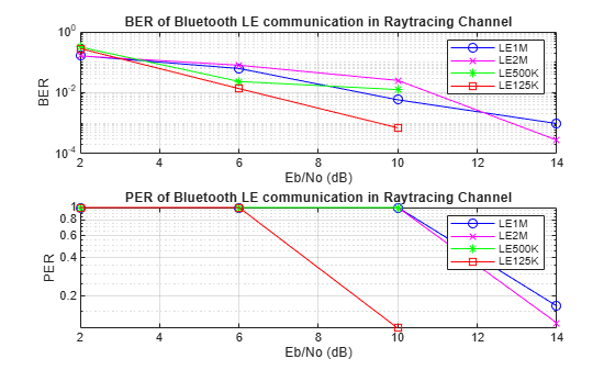
Mode LE1M, simulating for Raytracing Channel model, Eb/No = 2dB, data length = 128bytes, BER: 0.16422, PER: 1
Mode LE1M, simulating for Raytracing Channel model, Eb/No = 6dB, data length = 128bytes, BER: 0.062561, PER: 1
Mode LE1M, simulating for Raytracing Channel model, Eb/No = 10dB, data length = 128bytes, BER: 0.0058651, PER: 1
Mode LE1M, simulating for Raytracing Channel model, Eb/No = 14dB, data length = 128bytes, BER: 0.00097752, PER: 0.16667
Mode LE1M, simulating for Raytracing Channel model, Eb/No = 18dB, data length = 128bytes, BER: 0, PER: 0
Mode LE1M, simulating for Raytracing Channel model, Eb/No = 22dB, data length = 128bytes, BER: 0, PER: 0
Mode LE2M, simulating for Raytracing Channel model, Eb/No = 2dB, data length = 128bytes, BER: 0.16227, PER: 1
Mode LE2M, simulating for Raytracing Channel model, Eb/No = 6dB, data length = 128bytes, BER: 0.080156, PER: 1
Mode LE2M, simulating for Raytracing Channel model, Eb/No = 10dB, data length = 128bytes, BER: 0.025415, PER: 1
Mode LE2M, simulating for Raytracing Channel model, Eb/No = 14dB, data length = 128bytes, BER: 0.00027929, PER: 0.12245
Mode LE2M, simulating for Raytracing Channel model, Eb/No = 18dB, data length = 128bytes, BER: 0, PER: 0
Mode LE2M, simulating for Raytracing Channel model, Eb/No = 22dB, data length = 128bytes, BER: 0, PER: 0
Mode LE500K, simulating for Raytracing Channel model, Eb/No = 2dB, data length = 128bytes, BER: 0.31574, PER: 1
Mode LE500K, simulating for Raytracing Channel model, Eb/No = 6dB, data length = 128bytes, BER: 0.02346, PER: 1
Mode LE500K, simulating for Raytracing Channel model, Eb/No = 10dB, data length = 128bytes, BER: 0.012708, PER: 1
Mode LE500K, simulating for Raytracing Channel model, Eb/No = 14dB, data length = 128bytes, BER: 0, PER: 0
Mode LE500K, simulating for Raytracing Channel model, Eb/No = 18dB, data length = 128bytes, BER: 0, PER: 0
Mode LE500K, simulating for Raytracing Channel model, Eb/No = 22dB, data length = 128bytes, BER: 0, PER: 0
Mode LE125K, simulating for Raytracing Channel model, Eb/No = 2dB, data length = 128bytes, BER: 0.2825, PER: 1
Mode LE125K, simulating for Raytracing Channel model, Eb/No = 6dB, data length = 128bytes, BER: 0.013685, PER: 1
Mode LE125K, simulating for Raytracing Channel model, Eb/No = 10dB, data length = 128bytes, BER: 0.00070598, PER: 0.11111
Mode LE125K, simulating for Raytracing Channel model, Eb/No = 14dB, data length = 128bytes, BER: 0, PER: 0
Mode LE125K, simulating for Raytracing Channel model, Eb/No = 18dB, data length = 128bytes, BER: 0, PER: 0
Mode LE125K, simulating for Raytracing Channel model, Eb/No = 22dB, data length = 128bytes, BER: 0, PER: 0
Results and Visualizations
Specify the marker, color, and space for the legend variable.
marker = "ox*s";
color = "bmgr";
legendVar = strings(numMode,1);
Plot the BER and the PER curves for each PHY modes.
for countMode = 1:numMode
    subplot(2,1,1),semilogy(EbNo,ber(countMode,:).',"-"+marker{1}(countMode)+color{1}(countMode));
    hold on;
    legendVar(countMode) = simMode(countMode);

    subplot(2,1,2),semilogy(EbNo,per(countMode,:).',"-"+marker{1}(countMode)+color{1}(countMode));
    hold on;
    legendVar(countMode) = simMode(countMode);
end

subplot(2,1,1),
grid on;
xlabel("Eb/No (dB)");
ylabel("BER");
legend(legendVar);
title(join(["BER of Bluetooth LE communication in ",channelModel],""));

subplot(2,1,2),
grid on;
xlabel("Eb/No (dB)");
ylabel("PER");
legend(legendVar);
title(join(["PER of Bluetooth LE communication in ",channelModel],""));
Visualize Raytracing Model
If the fading channel is "Raytracing Channel", configure and display a conference room environment to simulate Bluetooth LE communication.
if (channelModel=="Raytracing Channel")
    visualVar = visualVar{end,end};

    % Show conference room
    viewer = siteviewer(SceneModel=visualVar.MapFileName);

    % Set the icons for transmit site and receiver site
    show(visualVar.TxSite,Icon="bleTxIcon.png");
    show(visualVar.RxSite,Icon="bleRxIcon.png");

    % Plot the rays in the site viewer
    plot(visualVar.Rays,Type="power",ColorLimits=[-30 0]);
end
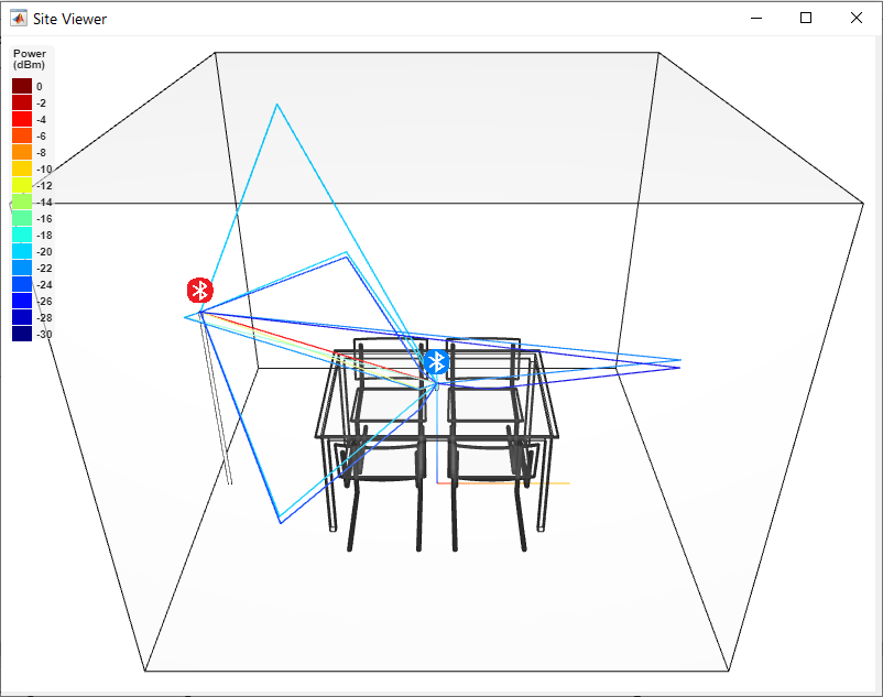
The preceding scenario consists of a 3-D indoor conference room, where the blue Bluetooth icon indicates the transmit site and the red Bluetooth icon indicates the receiver site. The rays in the scenario contain LOS components and NLOS components. Each ray reflects its color based on its path loss value. All the rays converge at the receiver site after zero, one, or two interactions (such as reflection and scattering) with a reflecting surface.
Further Exploration
You can further explore this example by increasing the maxNumErrors and maxNumPackets parameters. These BER and PER results are obtained by using this configuration.
dataLength— 128 bytesmaxNumErrors— 100maxNumPackets— 1000phyMode— LE1MchannelModel— Rician, Rayleigh and Raytracing channel model
To compensate for the fading channel effects, channel equalization is added to the simulation.
This figure shows the BER and PER obtained for three scenarios:
AWGN: Simulation does not contain any impairments.
Fading Channel: Simulation contains RF impairments and fading channel conditions.
Fading Channel with Equalizer: Simulation contains RF impairments and fading channel conditions with equalization.
LE1M in Rician Channel Model

LE1M in Rayleigh Channel Model

LE1M in Raytracing Channel Model

The reference Eb/No values generated based on the Bluetooth LE specification includes a margin for RF impairments are not simulated in the example. As a result, these simulation results outperform the standard reference results. If you modify this example to include additional impairments such as frequency drift and interference, the BER and PER values increase with respect to the reference Eb/No values specified in [2].
Appendix
The example uses these helpers.
helperBLEImpairmentsInit— Initialize RF impairment parametershelperBLEImpairmentsAddition— Add RF impairments to the Bluetooth LE waveformhelperBluetoothChannelInit— Initialize fading channel parametershelperBLEPracticalReceiver— Demodulate and decode the received signal
Selected Bibliography
[1] “Bluetooth® Technology Website – The Official Website for the Bluetooth Wireless Technology. Get up to Date Specifications, News, and Development Info.” Accessed September 30, 2024. https://www.bluetooth.com/.
[2] Bluetooth® Technology Website. "Core Specification," September 30, 2024. https://www.bluetooth.com/specifications/specs/core-specification-6-0/.
[3] “M.1225: Guidelines for Evaluation of Radio Transmission Technologies for IMT-2000.” Accessed September 30, 2024. https://www.itu.int/rec/R-REC-M.1225/en.
See Also
Functions
Topics
- Add RF Impairments and Fading Channel Model to Bluetooth LE Waveform in an Indoor Environment
- End-to-End Bluetooth LE PHY Simulation Using Path Loss Model, RF Impairments, and AWGN
- End-to-End Bluetooth BR/EDR PHY Simulation with Path Loss, RF Impairments, and AWGN
- End-to-End Bluetooth LE PHY Simulation with AWGN, RF Impairments and Corrections