comm.RSDecoder
Decode data using Reed-Solomon decoder
Description
The comm.RSDecoder
System object™ recovers a message vector from a Reed-Solomon (RS) codeword vector. For proper
decoding, the property values for this object must match the property values in the
corresponding comm.RSEncoder object. For more information, see
Algorithms.
To decode data using an RS-coding scheme:
Create the
comm.RSDecoderobject and set its properties.Call the object with arguments, as if it were a function.
To learn more about how System objects work, see What Are System Objects?
Creation
Syntax
Description
dec = comm.RSDecoderdec, that applies RS decoding.
dec = comm.RSDecoder(N,K)CodewordLength to
N and MessageLength to
K. For example, comm.RSDecoder(7,3) creates a
(7,3) RS decoder object.
dec = comm.RSDecoder(N,K,GP)GeneratorPolynomial to
GP and GeneratorPolynomialSource to 'Property'.
dec = comm.RSDecoder(N,K,GP,S)ShortMessageLength to
S and ShortMessageLengthSource to 'Property'.
dec = comm.RSDecoder(___,Name,Value)comm.RSDecoder(BitInput="true") creates an RS decoder object
configured to decode an input column vector of bits.
Properties
Usage
Description
Y = dec(X)CodewordLength,MessageLength) RS decoder. This
syntax applies when you set NumCorrectedErrorsOutputPort to false. For information
about the input and output lengths when you run the object, see Input and Output Signal Lengths in BCH and RS System Objects.
Y = dec(X,erasures)erasures input vector to erase symbols of the input
codewords in X. This syntax
applies when you set ErasuresInputPort to
true.
[
decodes using inputs from either of the previous syntaxes, and returns the RS-decoded
output vector Y,err] = dec(___)Y and the
number of corrected symbols in output vector err. A value of
-1 in the ith element of the error output vector
indicates that a decoding error occurred for that codeword. This syntax applies when you
set NumCorrectedErrorsOutputPort to true.
Input Arguments
Output Arguments
Object Functions
To use an object function, specify the
System object as the first input argument. For
example, to release system resources of a System object named obj, use
this syntax:
release(obj)
Examples
Transmit an RS-encoded, 8-DPSK-modulated symbol stream through an AWGN channel. After channel filtering demodulate and decode the received signal, and then count errors.
M = 8;
rsEnc = comm.RSEncoder;
rsDec = comm.RSDecoder;
errorRate = comm.ErrorRate(ComputationDelay=3);

for counter = 1:20
    data = randi([0 7], 30, 1);
    encodedData = rsEnc(data);
    modSignal = dpskmod(encodedData,M);
    receivedSignal = awgn(modSignal,10);
    demodSignal = dpskdemod(receivedSignal,M);
    receivedSymbols = rsDec(demodSignal);
    errorStats = errorRate(data,receivedSymbols);
end

fprintf('Error rate = %f\nNumber of errors = %d\n', ...
    errorStats(1), errorStats(2))
Error rate = 0.128978
Number of errors = 77
Transmit Reed-Solomon encoded data using QPSK over an AWGN channel. Demodulate and decode the received signal and collect error statistics. Compute the theoretical bit error rate (BER) for coded and noncoded data. Plot the BER results to compare performance.
Define the example parameters.
rng(1993);     % Seed random number generator for repeatable results
M = 4;         % Modulation order
bps = log2(M); % Bits per symbol
N = 7;         % RS codeword length
K = 5;         % RS message length
Create AWGN channel and error rate objects.
awgnChannel = comm.AWGNChannel( ...
    BitsPerSymbol=bps);
errorRate = comm.ErrorRate;
Create a (7,5) Reed-Solomon encoder and decoder pair that accepts bit inputs.
rsEncoder = comm.RSEncoder( ...
    BitInput=true, ...
    CodewordLength=N, ...
    MessageLength=K);
rsDecoder = comm.RSDecoder( ...
    BitInput=true, ...
    CodewordLength=N, ...
    MessageLength=K);
Set the range of values and account for RS coding gain. Initialize the error statistics matrix.
ebnoVec = (3:0.5:8)';
ebnoVecCodingGain = ...
    ebnoVec + 10*log10(K/N); % Account for RS coding gain
errorStats = zeros(length(ebnoVec),3);
Estimate the bit error rate for each value. The simulation runs until either 100 errors or bits is encountered. The simulation loop encodes and modulates random data, filters the signal through an AWGN channel, demodulate and decodes the signal, and then computes error statistics.
for i = 1:length(ebnoVec)
    awgnChannel.EbNo = ebnoVecCodingGain(i);
    reset(errorRate)
    while errorStats(i,2) < 100 && errorStats(i,3) < 1e7
        data = randi([0 1],1500,1);
        encData = rsEncoder(data);
        modData = pskmod(encData,M,InputType='bit');
        rxSig = awgnChannel(modData);
        rxData = pskdemod(rxSig,M,OutputType='bit');
        decData = rsDecoder(rxData);
        errorStats(i,:) = errorRate(data,decData);
    end
end
Fit a curve to the BER data using berfit. Generate an estimate of QPSK performance with and without coding by using the bercoding and berawgn functions.
berCurveFit = berfit(ebnoVecCodingGain,errorStats(:,1));
berwCoding = bercoding(ebnoVec,'RS','hard',N,K,'psk',M,'nondiff');
berNoCoding = berawgn(ebnoVec,'psk',M,'nondiff');
Plot the RS-coded BER data, curve fit of the BER data, theoretical performance with RS coding, and theoretical performance without RS coding. The (7,5) RS code improves the required to achieve a bit error rate by approximately 1.2 dB.
semilogy(ebnoVecCodingGain,errorStats(:,1),'b*', ...
    ebnoVecCodingGain,berCurveFit,'c-', ...
    ebnoVecCodingGain,berwCoding,'r', ...
    ebnoVec,berNoCoding)
ylabel('BER')
xlabel('Eb/No (dB)')
legend( ...
    'RS-coded BER','Curve fit', ...
    'Theory with coding','Theory no coding')
grid

Transmit a shortened, RS-encoded, 256-QAM-modulated symbol stream through an AWGN channel. Then demodulate, decode, and count errors.
Set the parameters for the Reed-Solomon code, where N is the codeword length, K is the nominal message length, and S is the shortened message length. Set the modulation order, M, and the number of frames, L.
N = 255;
K = 239;
S = 188;
M = 256;
L = 50;
bps = log2(M);
Create an AWGN channel System object and an error rate System object.
awgnChan = comm.AWGNChannel( ...
    NoiseMethod='Signal to noise ratio (Eb/No)', ...
    EbNo=15, ...
    BitsPerSymbol=bps);
errorRate = comm.ErrorRate(ComputationDelay=3);
Create the Reed-Solomon generator polynomial from the DVB-T standard.
gp = rsgenpoly(N,K,[],0);
Create a Reed-Solomon encoder and decoder pair using the shortened message length, S, and the DVB-T generator polynomial, gp.
enc = comm.RSEncoder(N,K,gp,S);
dec = comm.RSDecoder(N,K,gp,S);
Generate random symbol frames whose length equals one message block. Encode, modulate, apply AWGN, demodulate, decode, and collect statistics.
for counter = 1:L
    data = randi([0 1],S*bps,1);
    encodedData = enc(bit2int(data,bps));
    modSignal = qammod(encodedData,M,UnitAveragePower=true);
    rxSignal = awgnChan(modSignal);
    demodSignal = qamdemod(rxSignal,M,UnitAveragePower=true);
    rxBits = dec(demodSignal);
    dataOut = int2bit(rxBits,bps);
    errorStats = errorRate(data(:),dataOut(:));
end
Display the error rate and number of errors.
fprintf('Error rate = %5.2e\nNumber of errors = %d\n', ...
    errorStats(1), errorStats(2))
Error rate = 2.01e-02
Number of errors = 1514
This example shows how to configure the comm.RSEncoder and comm.RSDecoder System objects to perform Reed-Solomon (RS) block coding with erasures when simulating a communications system. A codeword with erasures can have those erasures in either message symbols or parity symbols. A punctured codeword has only parity symbols removed, and a shortened codeword has only message symbols removed.
RS decoders can correct both errors and erasures. A receiver that identifies the most unreliable symbols in a given codeword can generate symbol erasures and replace those symbols with zeros. When sending a symbol to the decoder, the receiver passes a flag to the decoder to indicate if the symbol is an erasure rather than a valid code symbol. In a similar fashion, the encoder can apply a puncture pattern that always removes specific parity symbols from its output. Given the puncture pattern, the decoder inserts zeros in the puncture positions, and treats those symbols the same way it treats erasures. Punctured codes offer code rate flexibility, but at the expense of some error correction capability. For the same demodulator input energy per bit to noise power spectral density ratio (), shortened codes, however, achieve the same code rate flexibility without degrading the error correction performance.
In this example, you simulate a communications system that consists of a random source, an RS encoder, a 64-QAM modulator, an AWGN channel, a 64-QAM demodulator, and an RS decoder. You analyze the RS coding with erasures by comparing the channel bit error rate (BER) performance versus the coded BER performance. You obtain the channel BER by comparing inputs for the QAM modulator to outputs from the QAM demodulator and the coded BER by comparing inputs for the RS encoder to outputs from the RS decoder.
Initialization
The helperRSCodingConfig.m helper function initializes the simulation parameters and configures the comm.AWGNChannel and comm.ErrorRate System objects that simulate the communications system. The helper function also sets the uncoded ratio (EbNoUncoded) to 15 dB and the simulation stop criteria for 500 errors or a maximum bits are transmitted.
helperRSCodingConfig;
Configure RS Encoder/Decoder
This example uses a (63,53) RS code operating with a 64-QAM modulation scheme. This code can correct (63 – 53)/2 = 5 errors, or it can alternatively correct (63 – 53) = 10 erasures. For each codeword at the output of the 64-QAM demodulator, the receiver determines the six least reliable symbols using the helperRSCodingGetErasures.m helper function. The indices that point to the location of these unreliable symbols are an input to the RS decoder. The RS decoder treats these symbols as erasures resulting in an error correction capability of (10 – 6)/2 = 2 errors per codeword.
Create a comm.RSEncoder System object and set the BitInput property to false so that the encoder inputs and outputs are integer symbols.
N = 63;  % Codeword length
K = 53;  % Message length
rsEncoder = comm.RSEncoder(N,K,BitInput=false);
numErasures = 6;
Create a comm.RSDecoder System object that matches the configuration of the comm.RSEncoder object.
rsDecoder = comm.RSDecoder(N,K,BitInput=false);
Set the ErasuresInputPort property to true to specify erasures as an input to the decoder object.
rsDecoder.ErasuresInputPort = true;
Set the NumCorrectedErrorsOutputPort property to true so that the decoder outputs the number of corrected errors. A nonnegative value in the error output denotes the number of corrected errors in the input codeword. A value of –1 in the error output indicates a decoding error. A decoding error occurs when the input codeword has more errors than the error correction capability of the RS code.
rsDecoder.NumCorrectedErrorsOutputPort = true;
Stream Processing Loop
Simulate the communications system for an uncoded ratio of 15 dB. The uncoded is the ratio that would be measured at the input of the channel if there were no coding in the system.
Since the signal going into the AWGN channel is the encoded signal, you must convert the uncoded values so that they correspond to the energy ratio at the encoder output. This ratio is the coded ratio. If you input K symbols to the encoder and obtain N output symbols, then the energy relation is given by the K/N rate. Set the EbNo property of the AWGN channel object to the computed coded value.
EbNoCoded = EbNoUncoded + 10*log10(K/N);
channel.EbNo = EbNoCoded;
Loop the simulation until it reaches the target number of errors or the maximum number of transmissions.
chanErrorStats = zeros(3,1);
codedErrorStats = zeros(3,1);
correctedErrors = 0;
while (codedErrorStats(2) < targetErrors) && ...
        (codedErrorStats(3) < maxNumTransmissions)
The data symbols transmit one message word at a time. Each message word has K symbols in the range [0, N].
data = randi([0 N],K,1);
Encode the message word. The encoded word, encData, is (N – numPunc) symbols long.
encData = rsEncoder(data);
Modulate encoded data and add noise. Then demodulate channel output.
    modData = qammod(encData,M);
    chanOutput = channel(modData);
    demodData = qamdemod(chanOutput,M);
Use the helperRSCodingGetErasures.m helper function to find the six least reliable symbols and generate an erasures vector. The length of the erasures vector must be equal to the number of symbols in the demodulated codeword. A one in the ith element of the vector erases the ith symbol in the codeword. Zeros in the vector indicate no erasures.
erasuresVec = helperRSCodingGetErasures(chanOutput,numErasures);
Decode the data. Log the number of errors corrected by the RS decoder.
    [estData,errs] = rsDecoder(demodData,erasuresVec);
    if (errs >= 0)
        correctedErrors = correctedErrors + errs;
    end
When computing the channel and coded BERs, convert integers to bits.
    chanErrorStats(:,1) = ...
        chanBERCalc(int2bit(encData,log2(M)), ...
            int2bit(demodData,log2(M)));
    codedErrorStats(:,1) = ...
        codedBERCalc(int2bit(data,log2(M)), ...
            int2bit(estData,log2(M)));
end
The error rate measurement objects, chanBERCalc and codedBERCalc, output 3-by-1 vectors containing BER measurement updates, the number of errors, and the total number of bit transmissions. Display the channel BER, the coded BER and the total number of errors corrected by the RS decoder.
chanBitErrorRate = chanErrorStats(1)
chanBitErrorRate =
0.0017
codedBitErrorRate = codedErrorStats(1)
codedBitErrorRate =
0
totalCorrectedErrors = correctedErrors
totalCorrectedErrors =
882
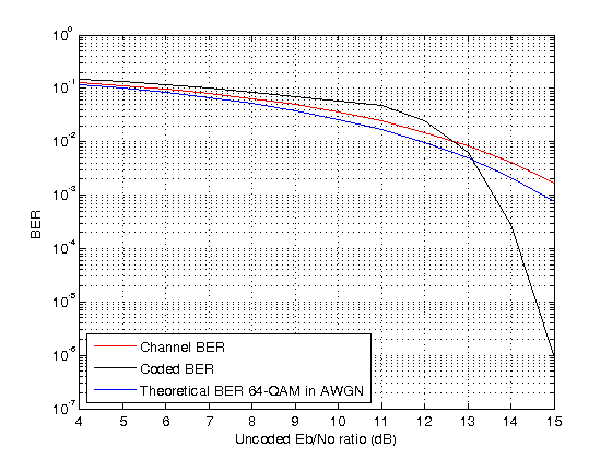
To run the simulation for a set of values, you can add a for-loop around the processing loop above. For a simulation with uncoded values in the range 4:15 dB, a target number of errors equal to 5000, and maximum number of transmissions equal to , the results in the figure show that the channel BER is worse than the theoretical 64-QAM BER because is reduced by the code rate.
Helper Functions
helperRSCodingConfig.mhelperRSCodingGetErasures.m
This example shows how to configure the comm.RSEncoder and comm.RSDecoder System objects to perform Reed-Solomon (RS) block coding with erasures and puncture codes when simulating a communications system. An encoder can generate punctures to remove specific parity symbols from its output. Given the puncture pattern, the decoder inserts zeros in the puncture positions and treats those symbols as erasures. The decoder treats encoder-generated punctures and receiver-generated erasures in exactly the same way when it decodes. Puncturing provides code rate flexibility, but at the expense of some error correction capability.
In this example, you simulate a communications system that consists of a random source, an RS encoder, a 64-QAM modulator, an AWGN channel, a 64-QAM demodulator, and an RS decoder. You analyze the RS coding with erasures and puncturing by comparing the channel bit error rate (BER) performance versus the coded BER performance. You obtain the channel BER by comparing inputs for the QAM modulator to outputs from the QAM demodulator and the coded BER by comparing inputs for the RS encoder to outputs from the RS decoder.
Initialization
The helperRSCodingConfig.m helper function initializes the simulation parameters and configures the comm.AWGNChannel and comm.ErrorRate System objects that simulate the communications system. The helper function also sets the uncoded ratio (EbNoUncoded) to 15 dB and the simulation stop criteria for 500 errors or a maximum bits are transmitted.
helperRSCodingConfig;
Configure RS Encoder/Decoder
This example uses the same (63,53) RS code operating with a 64-QAM modulation scheme that is configured for erasures and code puncturing. The RS algorithm decodes receiver-generated erasures and corrects encoder-generated punctures. For each codeword, the sum of the punctures and erasures cannot exceed twice the error-correcting capability of the code.
Create a comm.RSEncoder System object and set the BitInput property to false so that the encoder inputs and outputs are integer symbols.
N = 63;  % Codeword length
K = 53;  % Message length
rsEncoder = comm.RSEncoder(N,K,BitInput=false);
numErasures = 6;
Create a comm.RSDecoder System object that matches the configuration of the comm.RSEncoder object. Then set the ErasuresInputPort property to true to specify erasures as an input to the decoder object.
rsDecoder = comm.RSDecoder(N,K,BitInput=false);
rsDecoder.ErasuresInputPort = true;
To enable code puncturing, set the PuncturePatternSource property to 'Property' and set the PuncturePattern property to the desired puncture pattern vector. The same puncture vector must be specified in both the encoder and decoder. This example punctures two symbols from each codeword. Values of 1 in the puncture pattern vector indicate nonpunctured symbols, and values of 0 indicate punctured symbols.
numPuncs = 2;
rsEnc.PuncturePatternSource = 'Property';
rsEnc.PuncturePattern = [ones(N-K-numPuncs,1); zeros(numPuncs,1)];

rsDec.PuncturePatternSource = 'Property';
rsDec.PuncturePattern = rsEnc.PuncturePattern;
Stream Processing Loop
Simulate the communications system for an uncoded ratio of 15 dB. The uncoded is the ratio that would be measured at the input of the channel if there were no coding in the system.
Since the signal going into the AWGN channel is the encoded signal, you must convert the uncoded values so that they correspond to the energy ratio at the encoder output. This ratio is the coded ratio. If you input K symbols to the encoder and obtain N output symbols, then the energy relation is given by the K/N rate. Since the length of the codewords generated by the RS encoder is reduced by the number of punctures specified in the puncture pattern vector, the value of the coded ratio needs to be adjusted to account for these punctures. In this example, the number of output symbols is (N – numPuncs) and the uncoded ratio relates to the coded as shown below. Set the EbNo property of the AWGN channel object to the computed coded value.
EbNoCoded = EbNoUncoded + 10*log10(K/(N - numPuncs));
channel.EbNo = EbNoCoded;
Loop the simulation until it reaches the target number of errors or the maximum number of transmissions.
chanErrorStats = zeros(3,1);
codedErrorStats = zeros(3,1);
correctedErrors = 0;
while (codedErrorStats(2) < targetErrors) && ...
        (codedErrorStats(3) < maxNumTransmissions)
The data symbols transmit one message word at a time. Each message word has K symbols in the range [0, N].
data = randi([0 N],K,1);
Encode the message word. The encoded word, encData, is (N – numPunc) symbols long.
encData = rsEncoder(data);
Modulate encoded data and add noise. Then demodulate channel output.
    modData = qammod(encData,M);
    chanOutput = channel(modData);
    demodData = qamdemod(chanOutput,M);
Use the helperRSCodingGetErasures.m helper function to find the six least reliable symbols and generate an erasures vector. The length of the erasures vector must be equal to the number of symbols in the demodulated codeword. A one in the ith element of the vector erases the ith symbol in the codeword. Zeros in the vector indicate no erasures.
erasuresVec = helperRSCodingGetErasures(chanOutput,numErasures);
Decode the data. Log the number of errors corrected by the RS decoder.
    [estData,errs] = rsDecoder(demodData,erasuresVec);
    if (errs >= 0)
        correctedErrors = correctedErrors+errs;
    end
When computing the channel and coded BERs, convert integers to bits.
    chanErrorStats(:,1) = ...
        chanBERCalc(int2bit(encData,log2(M)), ...
            int2bit(demodData,log2(M)));
    codedErrorStats(:,1) = ...
        codedBERCalc(int2bit(data,log2(M)), ...
            int2bit(estData,log2(M)));
end
The error rate measurement objects, chanBERCalc and codedBERCalc, output 3-by-1 vectors containing BER measurement updates, the number of errors, and the total number of bit transmissions. Display the channel BER, the coded BER and the total number of errors corrected by the RS decoder.
chanBitErrorRate = chanErrorStats(1)
chanBitErrorRate =
0.0015
codedBitErrorRate = codedErrorStats(1)
codedBitErrorRate =
0
totalCorrectedErrors = correctedErrors
totalCorrectedErrors =
632
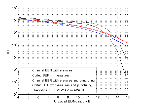
To run the simulation for a set of values, you can add a for-loop around the processing loop above. For a simulation with uncoded values in the range 4:15 dB, a target number of errors equal to 5000, and maximum number of transmissions equal to , the figure compares results for:
RS coding with only erasures
RS coding with erasures and puncturing
Theoretical BER for 64-QAM
The coded is slightly higher than the channel , so the channel BER is slightly better in the punctured case. On the other hand, the coded BER is worse in the punctured case because the two punctures reduce the error correcting capability of the code by one, leaving it able to correct only (10 – 6 – 2) / 2 = 1 error per codeword.
Help Functions
helperRSCodingConfig.mhelperRSCodingGetErasures.m
This example shows how to configure the comm.RSEncoder and comm.RSDecoder System objects to perform Reed-Solomon (RS) block coding that shortens a (63,53) code to a (28,18) code. You simulate a communications system that consists of a random source, an RS encoder, a 64-QAM modulator, an AWGN channel, a 64-QAM demodulator, and an RS decoder.
In this example, you analyze the effects of RS coding with erasures, puncturing, and shortening by comparing the channel bit error rate (BER) performance versus the coded BER performance. You obtain the channel BER by comparing inputs for the QAM modulator to outputs from the QAM demodulator and the coded BER by comparing inputs for the RS encoder to outputs from the RS decoder. Puncturing is the removal of parity symbols from a codeword, and shortening is the removal of message symbols from a codeword. Puncturing has the benefit of making the code rate more flexible, at the expense of some error correction capability. Shortened codes achieve the same code rate flexibility without degrading the error correction performance for the same demodulator input .
Initialization
The helperRSCodingConfig.m helper function initializes the simulation parameters and configures the comm.AWGNChannel and comm.ErrorRate System objects that simulate the communications system. The helper function also sets the uncoded ratio (EbNoUncoded) to 15 dB and the simulation stop criteria for 500 errors or a maximum bits are transmitted.
helperRSCodingConfig;
Configure RS Encoder/Decoder
This example uses a (63,53) RS code operating with a 64-QAM modulation scheme. The RS coding operation includes erasures, puncturing, and code shortening. This example shows how to shorten the (63,53) code to a (28,18) code.
To shorten a (63,53) code by 10 symbols to a (53,43) code, you can simply enter 53 and 43 for the CodewordLength and MessageLength properties, respectively (since ). However, to shorten it by 35 symbols to a (28,18) code, you must explicitly specify that the symbols belong to the Galois field GF(26). Otherwise, the RS System objects assume that the code is shortened from a (31,21) code (since ).
Create a pair of comm.RSEncoder and comm.RSDecoder System objects so that they perform block coding with a (28,18) code shortened from a (63,53) code that is configured to input and output integer symbols. Configure the decoder to accept an erasure input and two punctures. For each codeword at the output of the 64-QAM demodulator, the receiver determines the six least reliable symbols by using the helperRSCodingGetErasures.m helper function. The indices that point to the location of these unreliable symbols are an input to the RS decoder.
N = 63;  % Codeword length
K = 53;  % Message length
S = 18;  % Shortenened message length
numErasures = 6;
numPuncs = 2;
rsEncoder = comm.RSEncoder(N,K, ...
    BitInput=false, ...
    PuncturePatternSource="Property", ...
    PuncturePattern = [ones(N-K-numPuncs,1); zeros(numPuncs,1)]);
rsDecoder = comm.RSDecoder(N,K, ...
    BitInput=false, ...
    ErasuresInputPort=true, ...
    PuncturePatternSource="Property", ...
    PuncturePattern = rsEncoder.PuncturePattern);
Set the shortened codeword length and message length values.
rsEncoder.ShortMessageLength = S;
rsDecoder.ShortMessageLength = S;
Specify the field of in the RS encoder/decoder System objects, by setting the PrimitivePolynomialSource property to 'Property' and the PrimitivePolynomial property to a sixth degree primitive polynomial.
primPolyDegree = 6;
rsEncoder.PrimitivePolynomialSource = 'Property';
rsEncoder.PrimitivePolynomial = ...
    int2bit(primpoly(primPolyDegree,'nodisplay'),7)';

rsDecoder.PrimitivePolynomialSource = 'Property';
rsDecoder.PrimitivePolynomial = ...
    int2bit(primpoly(primPolyDegree,'nodisplay'),7)';
Stream Processing Loop
Simulate the communications system for an uncoded ratio of 15 dB. The uncoded is the ratio that would be measured at the input of the channel if there were no coding in the system.
Since the signal going into the AWGN channel is the encoded signal, you must convert the uncoded values so that they correspond to the energy ratio at the encoder output. This ratio is the coded ratio. If you input K symbols to the encoder and obtain N output symbols, then the energy relation is given by the K/N rate. Since the length of the codewords generated by the RS encoder is shortened and reduced by the number of punctures specified in the puncture pattern vector, the value of the coded ratio needs to be adjusted to account for the shortened code and the punctures. In this example, the number of output symbols is (N – numPuncs – S) and the uncoded ratio relates to the coded as shown below. Set the EbNo property of the AWGN channel object to the computed coded value.
EbNoCoded = EbNoUncoded + 10*log10(S/(N - numPuncs - K + S));
channel.EbNo = EbNoCoded;
Loop the simulation until it reaches the target number of errors or the maximum number of transmissions.
chanErrorStats = zeros(3,1);
codedErrorStats = zeros(3,1);
correctedErrors = 0;
while (codedErrorStats(2) < targetErrors) && ...
        (codedErrorStats(3) < maxNumTransmissions)
The data symbols transmit one message word at a time. Each message word has (K – S) symbols in the range [0, (2^primPolyDegree) – 1].
data = randi([0 2^primPolyDegree-1],S,1);
Encode the shortened message word. The encoded word encData is (N – numPuncs – S) symbols long.
encData = rsEncoder(data);
Modulate encoded data and add noise. Then demodulate channel output.
    modData = qammod(encData,M);
    chanOutput = channel(modData);
    demodData = qamdemod(chanOutput,M);
Use the helperRSCodingGetErasures.m helper function to find the six least reliable symbols and generate an erasures vector. The length of the erasures vector must be equal to the number of symbols in the demodulated codeword. A one in the ith element of the vector erases the ith symbol in the codeword. Zeros in the vector indicate no erasures.
erasuresVec = helperRSCodingGetErasures(chanOutput,numErasures);
Decode the data. Log the number of errors corrected by the RS decoder.
    [estData,errs] = rsDecoder(demodData,erasuresVec);
    if (errs >= 0)
        correctedErrors = correctedErrors + errs;
    end
When computing the channel and coded BERs, convert integers to bits.
    chanErrorStats(:,1) = ...
        chanBERCalc(int2bit(encData,log2(M)), ...
            int2bit(demodData,log2(M)));
    codedErrorStats(:,1) = ...
        codedBERCalc(int2bit(data,log2(M)), ...
            int2bit(estData,log2(M)));
end
The error rate measurement objects, chanBERCalc and codedBERCalc, output 3-by-1 vectors containing BER measurement updates, the number of errors, and the total number of bit transmissions. Display the channel BER, the coded BER, and the total number of errors corrected by the RS decoder.
chanBitErrorRate = chanErrorStats(1)
chanBitErrorRate =
0.0036
codedBitErrorRate = codedErrorStats(1)
codedBitErrorRate =
4.6399e-05
totalCorrectedErrors = correctedErrors
totalCorrectedErrors =
1416
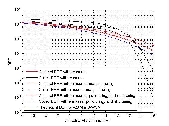
To run the simulation for a set of values, you can add a for-loop around the processing loop above. For a simulation with uncoded values in the range 4:15 dB, a target number of errors equal to 5000, and maximum number of transmissions equal to , the figure compares results for:
RS coding with only erasures
RS coding with erasures and puncturing
RS coding with erasures, puncturing, and shortening
Theoretical BER for 64-QAM
The BER out of the 64-QAM demodulator is worse with shortening than it is without shortening. The code rate of the shortened code is much lower than the code rate of the nonshortened code. Therefore, the coded into the demodulator is worse with shortening. A shortened code has the same error correcting capability as nonshortened code for the same , but the reduction in manifests in the form of a higher BER out of the RS decoder with shortening than without.
The coded is slightly higher than the channel , so the channel BER is slightly better than the coded BER in the shortened case. The degraded coded occurs because the code rate of the shortened code is lower than that of the nonshortened code. Shortening results in degraded coded BER, most noticeably at lower values.
Helper functions
helperRSCodingConfig.mhelperRSCodingGetErasures.m
Algorithms
References
[1] Blahut, Richard E. Algebraic Codes for Data Transmission. Cambridge University Press, 2003.
[2] Wicker, Stephen B., Error Control Systems for Digital Communication and Storage. Upper Saddle River, NJ, Prentice Hall, 1995.
[3] Clark, George C., and J. Bibb Cain. Error-Correction Coding for Digital Communications. Applications of Communications Theory. New York: Plenum Press, 1981.
[4] Berlekamp, Elwyn R., Algebraic Coding Theory, New York, McGraw-Hill, 1968.
Extended Capabilities
Version History
Introduced in R2012a