FBMC vs. OFDM Modulation
This example compares Filter Bank Multi-Carrier (FBMC) with Orthogonal Frequency Division Multiplexing (OFDM) and highlights the merits of the candidate modulation scheme for Fifth Generation (5G) communication systems.
FBMC was considered as an alternate waveform to OFDM in the 3GPP RAN study phase I during 3GPP Release 14.
Introduction
This example compares Filter Bank Multi-Carrier (FBMC) modulation with generic OFDM modulation. FBMC offers ways to overcome the known limitations of OFDM of reduced spectral efficiency and strict synchronization requirements. These advantages have led it to being considered as one of the modulation techniques for 5G communication systems [ 2, 4 ].
This example models Filter Bank Multi-Carrier modulation with configurable parameters and highlights the basic transmit and receive processing.
s = rng(211); % Set RNG state for repeatabilitySystem Parameters
Define system parameters for the example. You can modify these parameters to explore their impact on the system.
numFFT = 1024;           % Number of FFT points
numGuards = 212;         % Guard bands on both sides
K = 4;                   % Overlapping symbols, one of 2, 3, or 4
numSymbols = 100;        % Simulation length in symbols
bitsPerSubCarrier = 2;   % 2: 4QAM, 4: 16QAM, 6: 64QAM, 8: 256QAM
snrdB = 12;              % SNR in dB
Filter Bank Multi-Carrier Modulation
FBMC filters each subcarrier modulated signal in a multicarrier system. The prototype filter is the one used for the zero frequency carrier and is the basis for the other subcarrier filters. The filters are characterized by the overlapping factor, K which is the number of multicarrier symbols that overlap in the time domain. The prototype filter order can be chosen as 2*K-1 where K = 2, 3, or 4 and is selected as per the PHYDYAS project [ 1 ].
The current FBMC implementation uses frequency spreading. It uses an N*K length IFFT with symbols overlapped with a delay of N/2, where N is the number of subcarriers. This design choice makes it easy to analyze FBMC and compare with other modulation methods.
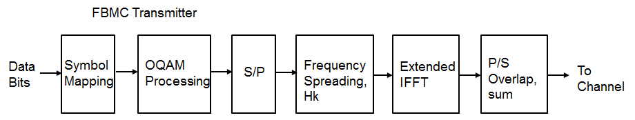
To achieve full capacity, offset quadrature amplitude modulation (OQAM) processing is employed. The real and imaginary parts of a complex data symbol are not transmitted simultaneously, as the imaginary part is delayed by half the symbol duration.
The transmit-end processing is shown in the following diagram.
% Prototype filter
switch K
    case 2
        HkOneSided = sqrt(2)/2;
    case 3
        HkOneSided = [0.911438 0.411438];
    case 4
        HkOneSided = [0.971960 sqrt(2)/2 0.235147];
    otherwise
        return
end
% Build symmetric filter
Hk = [fliplr(HkOneSided) 1 HkOneSided];

% Transmit-end processing
%   Initialize arrays
L = numFFT-2*numGuards;  % Number of complex symbols per OFDM symbol
KF = K*numFFT;
KL = K*L;
dataSubCar = zeros(L, 1);
dataSubCarUp = zeros(KL, 1);

sumFBMCSpec = zeros(KF*2, 1);
sumOFDMSpec = zeros(numFFT*2, 1);

numBits = bitsPerSubCarrier*L/2;    % account for oversampling by 2
inpData = zeros(numBits, numSymbols);
rxBits = zeros(numBits, numSymbols);
txSigAll = complex(zeros(KF, numSymbols));
symBuf = complex(zeros(2*KF, 1));

% Loop over symbols
for symIdx = 1:numSymbols

    % Generate mapped symbol data
    inpData(:, symIdx) = randi([0 1], numBits, 1);
    modData = qammod(inpData(:, symIdx), 2^bitsPerSubCarrier, ...
        'InputType', 'Bit', 'UnitAveragePower', true);

    % OQAM Modulator: alternate real and imaginary parts
    if rem(symIdx,2)==1     % Odd symbols
        dataSubCar(1:2:L) = real(modData);
        dataSubCar(2:2:L) = 1i*imag(modData);
    else                    % Even symbols
        dataSubCar(1:2:L) = 1i*imag(modData);
        dataSubCar(2:2:L) = real(modData);
    end

    % Upsample by K, pad with guards, and filter with the prototype filter
    dataSubCarUp(1:K:end) = dataSubCar;
    dataBitsUpPad = [zeros(numGuards*K,1); dataSubCarUp; zeros(numGuards*K,1)];
    X1 = filter(Hk, 1, dataBitsUpPad);
    % Remove 1/2 filter length delay
    X = [X1(K:end); zeros(K-1,1)];

    % Compute IFFT of length KF for the transmitted symbol
    txSymb = fftshift(ifft(X));

    % Transmitted signal is a sum of the delayed real, imag symbols
    symBuf = [symBuf(numFFT/2+1:end); complex(zeros(numFFT/2,1))];
    symBuf(KF+(1:KF)) = symBuf(KF+(1:KF)) + txSymb;

    % Compute power spectral density (PSD)
    currSym = complex(symBuf(1:KF));
    [specFBMC, fFBMC] = periodogram(currSym, hann(KF, 'periodic'), KF*2, 1);
    sumFBMCSpec = sumFBMCSpec + specFBMC;

    % Store transmitted signals for all symbols
    txSigAll(:,symIdx) = currSym;
end

% Plot power spectral density
sumFBMCSpec = sumFBMCSpec/mean(sumFBMCSpec(1+K+2*numGuards*K:end-2*numGuards*K-K));
plot(fFBMC-0.5,10*log10(sumFBMCSpec));
grid on
axis([-0.5 0.5 -180 10]);
xlabel('Normalized frequency');
ylabel('PSD (dBW/Hz)')
title(['FBMC, K = ' num2str(K) ' overlapped symbols'])
set(gcf, 'Position', figposition([15 50 30 30]));
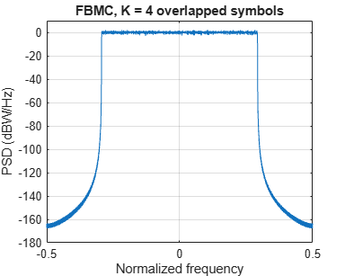
The power spectral density of the FBMC transmit signal is plotted to highlight the low out-of-band leakage.
OFDM Modulation with Corresponding Parameters
For comparison, we review the existing OFDM modulation technique, using the full occupied band, however, without a cyclic prefix.
for symIdx = 1:numSymbols

    inpData2 = randi([0 1], bitsPerSubCarrier*L, 1);
    modData = qammod(inpData2, 2^bitsPerSubCarrier, ...
        'InputType', 'Bit', 'UnitAveragePower', true);

    symOFDM = [zeros(numGuards,1); modData; zeros(numGuards,1)];
    ifftOut = sqrt(numFFT).*ifft(ifftshift(symOFDM));

    [specOFDM,fOFDM] = periodogram(ifftOut, rectwin(length(ifftOut)), ...
        numFFT*2, 1, 'centered');
    sumOFDMSpec = sumOFDMSpec + specOFDM;
end

% Plot power spectral density (PSD) over all subcarriers
sumOFDMSpec = sumOFDMSpec/mean(sumOFDMSpec(1+2*numGuards:end-2*numGuards));
figure;
plot(fOFDM,10*log10(sumOFDMSpec));
grid on
axis([-0.5 0.5 -180 10]);
xlabel('Normalized frequency');
ylabel('PSD (dBW/Hz)')
title(['OFDM, numFFT = ' num2str(numFFT)])
set(gcf, 'Position', figposition([46 50 30 30]));
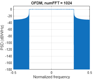
Comparing the plots of the spectral densities for OFDM and FBMC schemes, FBMC has lower side lobes. This allows a higher utilization of the allocated spectrum, leading to increased spectral efficiency.
FBMC Receiver with No Channel
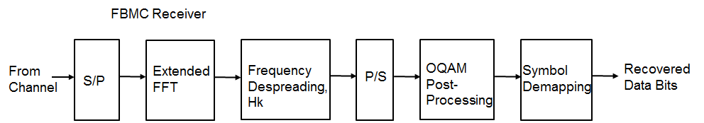
The example implements a basic FBMC demodulator and measures the BER for the chosen configuration in the absence of a channel. The processing includes matched filtering followed by OQAM separation to form the received data symbols. These are de-mapped to bits and the resultant bit error rate is determined. In the presence of a channel, linear multi-tap equalizers may be used to mitigate the effects of frequency-selective fading.
The receive-end processing is shown in the following diagram.
BER = comm.ErrorRate;

% Process symbol-wise
for symIdx = 1:numSymbols
    rxSig = txSigAll(:, symIdx);

    % Add WGN
    rxNsig = awgn(rxSig, snrdB, 'measured');

    % Perform FFT
    rxf = fft(fftshift(rxNsig));

    % Matched filtering with prototype filter
    rxfmf = filter(Hk, 1, rxf);
    % Remove K-1 delay elements
    rxfmf = [rxfmf(K:end); zeros(K-1,1)];
    % Remove guards
    rxfmfg = rxfmf(numGuards*K+1:end-numGuards*K);

    % OQAM post-processing
    %  Downsample by 2K, extract real and imaginary parts
    if rem(symIdx, 2)
        % Imaginary part is K samples after real one
        r1 = real(rxfmfg(1:2*K:end));
        r2 = imag(rxfmfg(K+1:2*K:end));
        rcomb = complex(r1, r2);
    else
        % Real part is K samples after imaginary one
        r1 = imag(rxfmfg(1:2*K:end));
        r2 = real(rxfmfg(K+1:2*K:end));
        rcomb = complex(r2, r1);
    end
    %  Normalize by the upsampling factor
    rcomb = (1/K)*rcomb;

    % De-mapper: Perform hard decision
    rxBits(:, symIdx) = qamdemod(rcomb, 2^bitsPerSubCarrier, ...
        'OutputType', 'bit', 'UnitAveragePower', true);
end

% Measure BER with appropriate delay
BER.ReceiveDelay = bitsPerSubCarrier*KL;
ber = BER(inpData(:), rxBits(:));

% Display Bit error
disp(['FBMC Reception for K = ' num2str(K) ', BER = ' num2str(ber(1)) ...
    ' at SNR = ' num2str(snrdB) ' dB'])
FBMC Reception for K = 4, BER = 0 at SNR = 12 dB
% Restore RNG state
rng(s);
Conclusion and Further Exploration
The example presents the basic transmit and receive characteristics of the FBMC modulation scheme. Explore this example by changing the number of overlapping symbols, FFT lengths, guard band lengths, and SNR values.
Refer to UFMC vs. OFDM Modulation for an example that describes the Universal Filtered Multi-Carrier (UFMC) modulation scheme.
FBMC is considered advantageous in comparison to OFDM by offering higher spectral efficiency. Due to the per subcarrier filtering, it incurs a larger filter delay (in comparison to UFMC) and also requires OQAM processing, which requires modifications for MIMO processing.
Further explorations should include modifications for MIMO processing with more complete link-level processing including channel estimation and equalization [ 2 ].
Selected Bibliography
"FBMC physical layer: a primer", PHYDYAS EU FP7 Project 2010. https://www.ict-phydyas.org
Schellman, M., Zhao, Z., Lin, H., Siohan, P., Rajatheva, N., Luecken, V., Ishaque, A., "FBMC-based air interface for 5G mobile: Challenges and proposed solutions", CROWNCOM 2014, pp 102-107.
Farhang-Boroujeny, B., "OFDM versus filter bank multicarrier", IEEE® Signal Proc. Mag., vol. 28, pp. 92-112, May 2011.
Wunder, G., Kasparick, M., Wild, T., Schaich, F., Yejian Chen, Dryjanski, M., Buczkowski, M., Pietrzyk, S., Michailow, N., Matthe, M., Gaspar, I., Mendes, L., Festag, A., Fettweis, G., Dore, J.-B., Cassiau, N., Ktenas, D., Berg, V., Eged, B., Vago, P., "5GNOW: Intermediate frame structure and transceiver concepts", Globecom workshops, pp. 565-570, 2014.