Control of an Inverted Pendulum on a Cart
This example uses systune to control an inverted pendulum on a cart.
Pendulum/Cart Assembly
The cart/pendulum assembly is depicted in Figure 1 and modeled in Simulink® using Simscape™ Multibody™.

Figure 1: Inverted pendulum on a cart
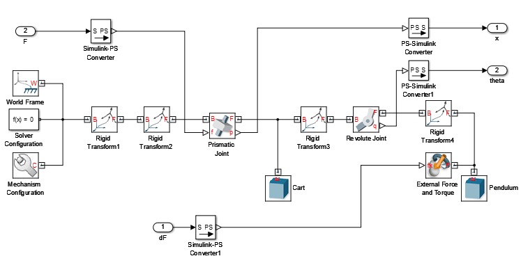
Figure 2: Simscape Multibody model
This system is controlled by exerting a variable force  on the cart. The controller needs to keep the pendulum upright while moving the cart to a new position or when the pendulum is nudged forward (impulse disturbance
  ).
).
Control Structure
The upright position is an unstable equilibrium for the inverted pendulum. The unstable nature of the plant makes the control task more challenging. For this example, you use the following two-loop control structure:
open_system('rct_pendulum.slx')
set_param('rct_pendulum','SimMechanicsOpenEditorOnUpdate','off');
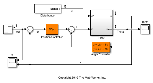
The inner loop uses a second-order state-space controller to stabilize the pendulum in its upright position ( control), while the outer loop uses a Proportional-Derivative (PD) controller to control the cart position. You use a PD rather than PID controller because the plant already provides some integral action.
Design Requirements
Use TuningGoal requirements to specify the desired closed-loop behavior. Specify a response time of 3 seconds for tracking a setpoint change in cart position  .
.
% Tracking of x command
req1 = TuningGoal.Tracking('xref','x',3);
To adequately reject impulse disturbances  on the tip of the pendulum, use an LQR penalty of the form

that emphasizes a small angular deviation  and limits the control effort
  .
.
% Rejection of impulse disturbance dF
Qxu = diag([16 1 0.01]);
req2 = TuningGoal.LQG('dF',{'Theta','x','F'},1,Qxu);
For robustness, require at least 6 dB of gain margin and 40 degrees of phase margin at the plant input.
% Stability margins
req3 = TuningGoal.Margins('F',6,40);
Finally, constrain the damping and natural frequency of the closed-loop poles to prevent jerky or underdamped transients.
% Pole locations
MinDamping = 0.5;
MaxFrequency = 45;
req4 = TuningGoal.Poles(0,MinDamping,MaxFrequency);
Control System Tuning
The closed-loop system is unstable for the initial values of the PD and state-space controllers (1 and  , respectively). You can use
 systune to jointly tune these two controllers. Use the slTuner interface to specify the tunable blocks and register the plant input F as an analysis point for measuring stability margins.
ST0 = slTuner('rct_pendulum',{'Position Controller','Angle Controller'});
addPoint(ST0,'F');
Next, use systune to tune the PD and state-space controllers subject to the performance requirements specified above. Optimize the tracking and disturbance rejection performance (soft requirements) subject to the stability margins and pole location constraints (hard requirements).
rng(0)
Options = systuneOptions('RandomStart',5);
[ST, fSoft] = systune(ST0,[req1,req2],[req3,req4],Options);
Final: Soft = 1.36, Hard = 0.99945, Iterations = 272
Final: Soft = 1.44, Hard = 0.99917, Iterations = 138
Final: Soft = 1.44, Hard = 0.99749, Iterations = 364
Final: Soft = 1.26, Hard = 0.99967, Iterations = 314
Final: Soft = 1.44, Hard = 0.99877, Iterations = 241
Final: Soft = 1.4, Hard = 0.99866, Iterations = 298
The best design achieves a value close to 1 for the soft requirements while satisfying the hard requirements (Hard<1). This means that the tuned control system nearly achieves the target performance for tracking and disturbance rejection while satisfying the stability margins and pole location constraints.
Validation
Use viewGoal to further analyze how the best design fares against each requirement.
figure('Position',[100   100   575   660])
viewGoal([req1,req3,req4],ST)
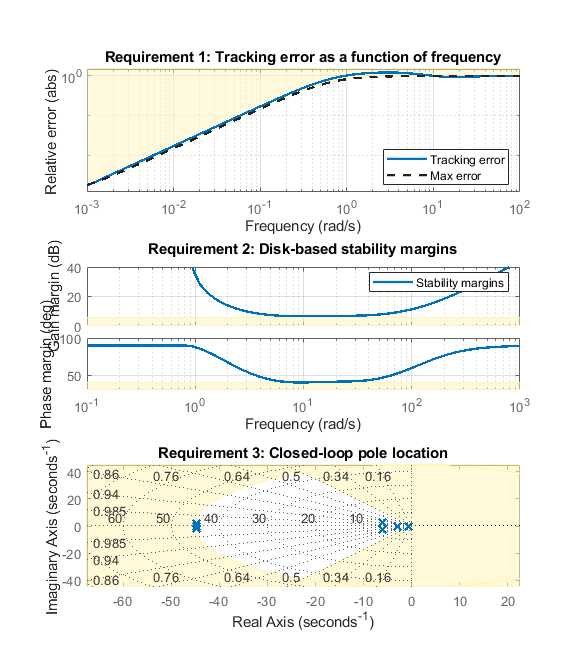
These plots confirm that the first two requirements are nearly satisfied while the last two are strictly enforced. Next, plot the responses to a step change in position and to a force impulse on the cart.
T = getIOTransfer(ST,{'xref','dF'},{'x','Theta'});
figure('Position',[100   100   650   420]);
subplot(121), step(T(:,1),10)
title('Tracking of set point change in position')
subplot(122), impulse(T(:,2),10)
title('Rejection of impulse disturbance')
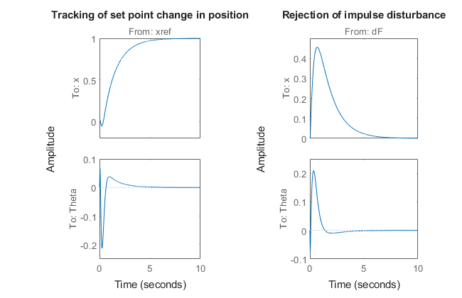
The responses are smooth with the desired settling times. Inspect the tuned values of the controllers.
C1 = getBlockValue(ST,'Position Controller')
C1 =

               s
  Kp + Kd * --------
             Tf*s+1

  with Kp = 5.89, Kd = 1.93, Tf = 0.051

Name: Position_Controller
Continuous-time PDF controller in parallel form.
C2 = zpk(getBlockValue(ST,'Angle Controller'))
C2 =

  -1614.3 (s+12.9) (s+4.304)
  --------------------------
     (s+135.2) (s-14.28)

Name: Angle_Controller
Continuous-time zero/pole/gain model.
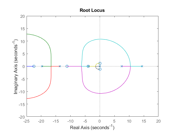
Note that the angle controller has an unstable pole that pairs up with the plant unstable pole to stabilize the inverted pendulum. To see this, get the open-loop transfer at the plant input and plot the root locus.
L = getLoopTransfer(ST,'F',-1);
figure
rlocus(L)
set(gca,'XLim',[-25 20],'YLim',[-20 20])
To complete the validation, upload the tuned values to Simulink and simulate the nonlinear response of the cart/pendulum assembly. A video of the resulting simulation appears below.
writeBlockValue(ST)
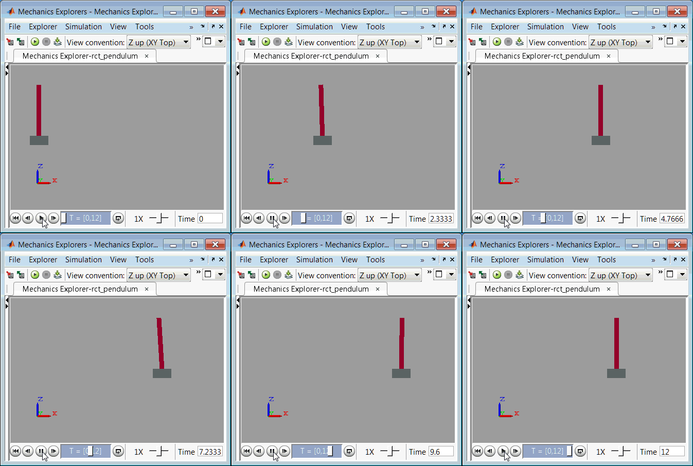
Figure 3: Cart/pendulum simulation with tuned controllers.
Close the model after simulation.
set_param('rct_pendulum','SimMechanicsOpenEditorOnUpdate','on');
close_system('rct_pendulum',0);
See Also
systune (Simulink Control Design) | slTuner (Simulink Control Design)
Topics
- Mark Signals of Interest for Control System Analysis and Design (Simulink Control Design)
- Create and Configure slTuner Interface to Simulink Model (Simulink Control Design)