PWM Peripheral Configuration
Map PWM peripherals in the Infineon AURIX model to peripheral registers in the MCU
Since R2024a
Description
Add-On Required: This feature requires the Embedded Coder Support Package for Infineon AURIX TC3x Microcontrollers add-on.
View and edit the module and channel settings of PWM peripherals in the Infineon® AURIX™ model.
Using the Peripheral Configuration tool, you can:
View and edit the module and channel of PWM peripherals.
Configure the global parameters. To set the group peripheral, select peripheral in BrowserPeripherals
PWM.The PWM Global parameters are available only if more than two PWM blocks are used in the model. For more, see Map Tasks and Peripherals Using Hardware Mapping.
Check for any conflicts between peripherals.
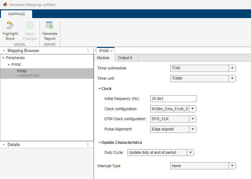
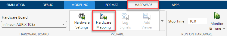
Open the PWM Peripheral Configuration
In the Simulink toolstrip, go to Hardware tab and click Hardware Mapping.
Parameters
Global parameters
Select to enable the PWM sync functionality between two PWM blocks.
Note
Enable sync group functionality parameter is displayed only if more than one PWM block is available in the model.
If you use sync functionality for two blocks PWM1 and PWM2 with same parameter configuration in the hardware mapping window except for the Pulse Alignment parameter set to
Edge alignedfor PWM1 block and the Pulse Alignment parameter set tocentre alignedfor PWM2 block, then the waveform generated by PWM1 block (IO_P02_0_pin=Z) leads the waveform generated by PWM2 block (IO_P02_8_pin=Z).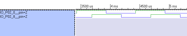
If you enable start/stop ports for the PWM blocks with sync group functionality, connect both input ports to a single block to ensure they receive the same value.
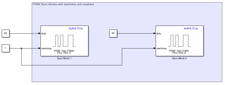
When you select this option, the dialog box displays the Drive Group and Trigger Group options. Two or more PWM blocks in the model enable these global parameters, since these parameters are implied for sync functionality.
The drive group lists all the PWM blocks used in the model. Select the PWM block from the list.
Dependencies
To enable the Drive Group parameter, select the Enable sync group functionality parameter.
The trigger group lists all the PWM blocks used in the model. Select the PWM block from the list.
The PWM generated from the trigger block syncs with the PWM generated from the drive block.
Dependencies
To enable the Trigger Group parameter, select the Enable sync group functionality parameter.
Module
Select the Timer Output Module (TOM) or ARU-connected Timer Output Module (ATOM) timer submodule.
Note
You must disable the EVADC G# and the corresponding GTM ADC trigger signal # parameters before changing the Timer submodule value.
Select the timer unit for PWM.
For example, TOM0, 0 represents the cluster number.
Dependencies
The Timer Unit options depends on the selection of Timer submodule. If TOM is set as Timer submodule, then the Timer unit list TOM# options. If ATOM is set as Timer submodule, then the Timer unit list ATOM# options.
Module > Clock
Specify the initial frequency (Hz) for PWM.
Select the PWM clock configuration. The PWM clock configuration parameters lists all the fixed clock and CMU clock options.
For example, if you select Timer submodule as
TOM, the clock configuration divider is represented as
IfxGtm_Cmu_Fxclk_#. When you select Timer submodule as
ATOM, the clock configuration divider is represented as
IfxGtm_Cmu_clk_#.
For TOM modules there are five different divide values based on the selection and for ATOM there are eight different selections of clock configuration.
TOM- FXCLK Divider 0 (20), FXCLK Divider 1 (24), FXCLK Divider 2 (28), FXCLK Divider 3 (212), and FXCLK Divider 4 (216)ATOM- CMUCLK Divider 0 (20), CMUCLK Divider 1 (21), CMUCLK Divider 2 (22), CMUCLK Divider 3 (23), CMUCLK Divider 4 (24), CMUCLK Divider 5 (25), CMUCLK Divider 6 (26), and CMUCLK Divider 7 (27).
Dependencies
Clock configuration depends on the selection made in Timer submodule.
If TOM submodule is selected, then fixed clocks are displayed.
If ATOM is selected, then configurable CMU clocks are displayed.
Specify the dead time module clock configuration.
Dependencies
DTM Clock configuration depends on the selection made in Timer submodule.
If TOM submodule is selected, then fixed clocks are displayed.
If ATOM is selected, then configurable CMU clocks are displayed.
Select the pulse alignment for PWM.
Select edge aligned if you want to generate edge aligned PWM pulse.
Select center aligned if you want to generate symmetric center aligned PWM pulse.
Note
If you choose Center aligned and the PWM
freq and duty inputs use different sampling times, you must disable the
Treat each discrete rate as a separate
task parameter to ensure correct PWM behaviour.
Module > Update Characteristics
Specify when to update the duty cycle.
Specify when to update the frequency.
Dependencies
To enable this parameter, set the Enable frequency input parameter in the PWM block in the Simulink® model.
Specify when to update the phase.
Dependencies
To enable this parameter, set the Enable phase input parameter in the PWM block in the Simulink model.
Specify the type of interrupt event for the PWM as one of these options.
None—Select this option when you do not want to specify an interrupt event.Period Interrupt—Select this option to specify an interrupt event at the end of every period.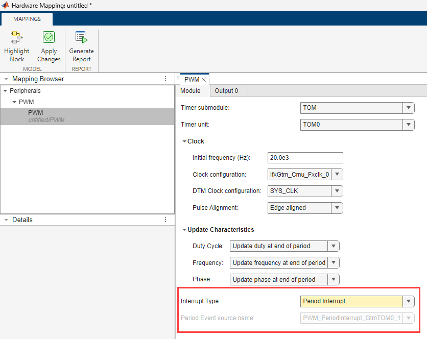
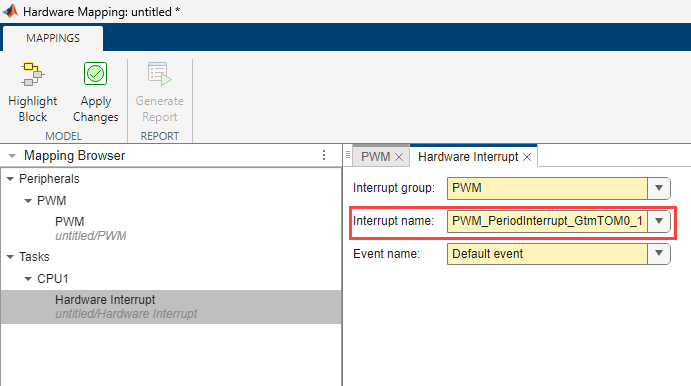
Selecting this option also enables the read-only parameter Period Event source name, which provides information on the source of the period interrupt. The source depends onModule, Timer submodule, and Timer unit parameters. You can map the name in the tasks (CPU1).
Duty Interrupt—Select this option to enable an interrupt at the start of every duty cycle.
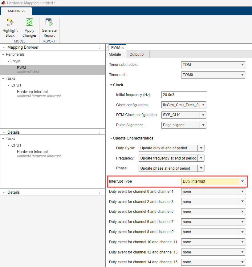
Specify the duty event based on the channel pair.
Channel pairs such as channel 0 and channel 1, channel 2 and channel 3, …. , channel 14 and channel 15, share same duty event sources. For example, if you select the channel 0 and channel 1 pair, the available duty options are:
IfxGtm_Pwm_SubModule_Ch_0IfxGtm_Pwm_SubModule_Ch_1
If you select the IfxGtm_Pwm_SubModule_Ch_0 event,
the block enables the read-only Duty Event source name
parameter in Output 0 tab.
Note
To select the duty event for the channel pairs, set the Number of
outputs parameter in the PWM block appropriately. For example,
set the Number of outputs parameter in the PWM block as
13 to use the Duty event for channel 12
and channel 13.
Dependencies
To enable this parameter, set Interrupt Type to
Duty Interrupt.
Output #
The number of outputs selected in the PWM block will appear in their respective output tabs of the PWM peripheral. Each of these outputs must be configured respectively.
Dependencies
The channel # list depends on
Timer Submodule (TOM or ATOM)
Timer unit (TOM# or ATOM#)
Select the PWM output pin channel.
Dependencies
The Output pin # list depends on
Timer Submodule (TOM or ATOM)
Timer unit (TOM# or ATOM#)
Channel
Select the output mode for the PWM pin(s).
Select the pin speed.
Select the pin voltage level.
Select the signal polarity of PWM channel.
Specify the PWM initial duty cycle in percentage. Range varies from 0-100%.
Enables the complementary output for PWM.
Select the PWM complementary output pin.
Dependencies
To enable the Complementary output pin parameter, select the Enable complementary output parameter.
Select the signal polarity of complementary pin.
Dependencies
To enable the Signal polarity of complementary pin parameter, select the Enable complementary output parameter.
Enables the dead time insertion.
Dependencies
To enable the Enable Dead time insertion parameter, select the Enable complementary output parameter.
Specify the PWM dead time for rising edge(s) in seconds.
For more information on standard dead time generation, see Dead-Time Module Properties.
Dependencies
To enable the Dead-time for rising edge(s) parameter, select the Enable Dead time insertion parameter.
Specify the PWM dead time for falling edge(s) in seconds.
For more information on standard dead time generation, see Dead-Time Module Properties.
Dependencies
To enable the Dead-time for falling edge(s) parameter, select the Enable Dead time insertion parameter.
Enable this parameter to trigger ADC conversion at the end of every period.
Note
You must have an EVADC block in the model to trigger ADC conversion.
Dependencies
The ADC trigger depends on
Timer Submodule (TOM or ATOM)
Timer unit (TOM# or ATOM#)
Channel
For more information on ADC trigger signal, see to EVADC Trigger Signals
select to trigger ADC conversion on channel group G#. For more information on ADC trigger signal, refer to EVADC Trigger Signals.
ADC trigger signal for the channel group.
Dependencies
To enable the GTM ADC trigger signal # parameter, select the EVADC G# parameter.
Enable this parameter to trigger SENT transmission at the end of every period.
To trigger SENT module, set the Trigger source parameter
to Hardware trigger and select Source of
hardware trigger in the corresponding SPC
Protocol tab of SENT
Peripheral Configuration window.
Select the SENT trigger signal.
The Sent trigger signal list depends on:
Channel # (
IfxGtm_Pwm_SubModule_Ch_#)Timer unit (
TOM#orATOM#)
For more information on SENT trigger signals, see SENT Trigger Signals.
Dependencies
To enable the Sent trigger signal parameter, select the SENT trigger parameter.
Select to enable EDSADC trigger.
Select the EDSADC trigger signal.
The Trigger signal list depends on:
Channel # (
IfxGtm_Pwm_SubModule_Ch_#)Timer unit (
TOM#orATOM#)
For more information on EDSADC trigger signals, see EDSADC Trigger Signals.
Dependencies
To enable the Trigger signal parameter, select the Enable EDSADC trigger parameter.
Specify the EDSADC channel to trigger form PWM block.
More About
Version History
Introduced in R2024a