Create Real-Time Clock Block to Display Time Using IO Device Builder App
This example shows how to use the IO Device Builder app to create a real-time clock (RTC) block that displays time.
An RTC is a crucial component in computing and electronic devices, providing accurate timekeeping through an independent binary-coded decimal (BCD) system. It features a time-of-day clock, calendar, and programmable alarm interrupt, which enables precise scheduling of operations or waking the device from low-power modes.
Prerequisites
Note: No circuit connections are required for this example.
This example uses STM32CubeMX tool to automatically generate all required driver files, eliminating the need for manual driver downloads. Perform these steps to configure the STM32CubeMX.
1. Start with a blank Simulink model.
2. Navigate to Modeling > Model Settings to open the Configuration Parameters dialog box.
3. In the Configuration Parameters dialog box, select Hardware Implementation and then select a STMicroelectronics® board from Hardware board drop-down list. The parameter under Hardware board settings are automatically populated to their default values.
4. Click Target hardware resources and then click Create in Build options.
5. In Create STM32CubeMX Project window, specify a project name (for example: rtcClockExample.ioc) and select the required hardware (for example, NUCLEO-F429ZI). This will generate the project folder in the selected directory.
6. Click OK.
7. In Target hardware resources > Build options, click Launch. This will launch STM32CubeMX.
8. In the STM32CubeMX window, navigate to Pinout & Configuration > Categories > Timers > RTC.
Ensure Activate Clock Source and Activate Calendar options are selected.
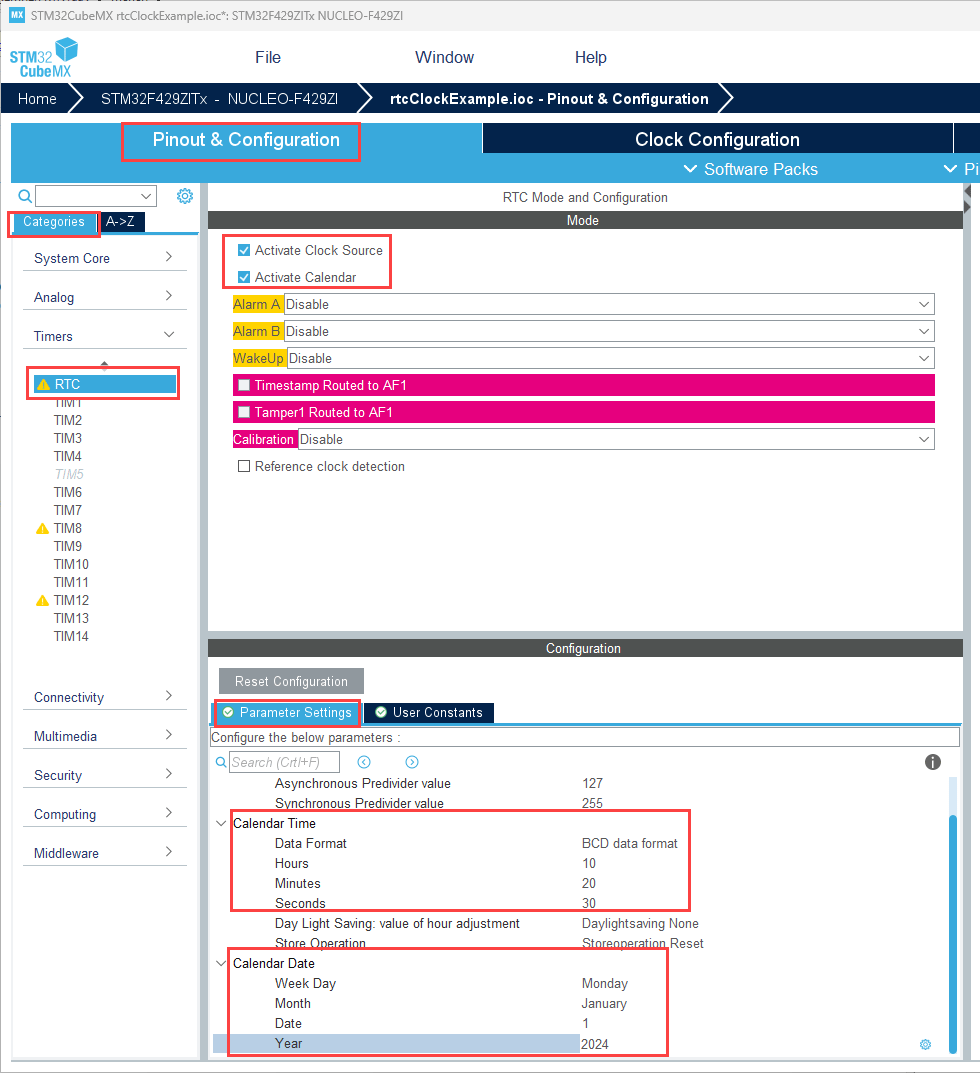
In the Parameter Settings pane, set values for Calendar Time and Calendar Date.
9. Navigate to Project Manager > Project and ensure that:
Do not generate the main() option is selected.
Generate Under Root option is cleared.

10. In the Advanced Settings tab:
Under Driver Selector, ensure HAL drivers are selected for the RTC.
In Generate Functions Calls, clear Do Not Generate Function Calls for all the peripheral initialization function calls.
Clear Visibility (Static) for all the peripheral initialization function calls.
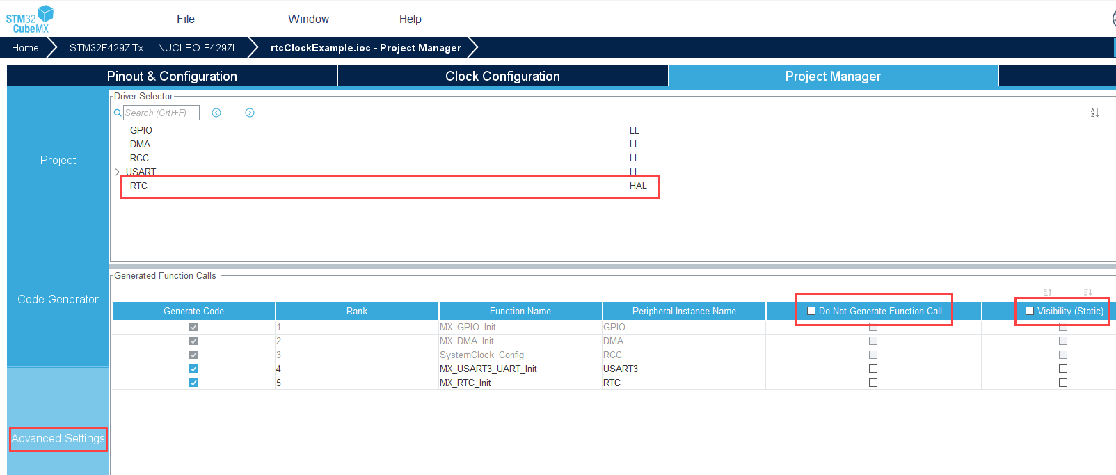
11. Click File and then Save project.
12. Close the STM32CubeMX tool and click OK in the Configuration Parameters dialog box.
Open the IO Device Builder App
To launch the IO Device Builder app, perform these steps in the Simulink Model that is already open.
On the Hardware tab of the Simulink model, click the arrow in the Prepare section. Under Design, choose IO Device Builder.
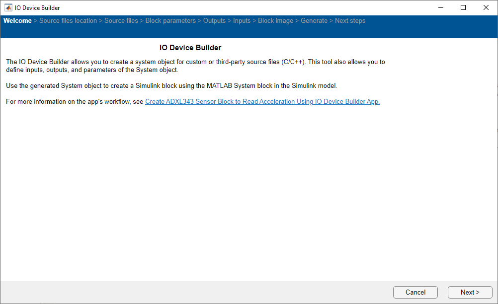
Select Working Directory and Add Third-party Source Files
Once the Source files location page loads, select the working directory and add third-party source files.
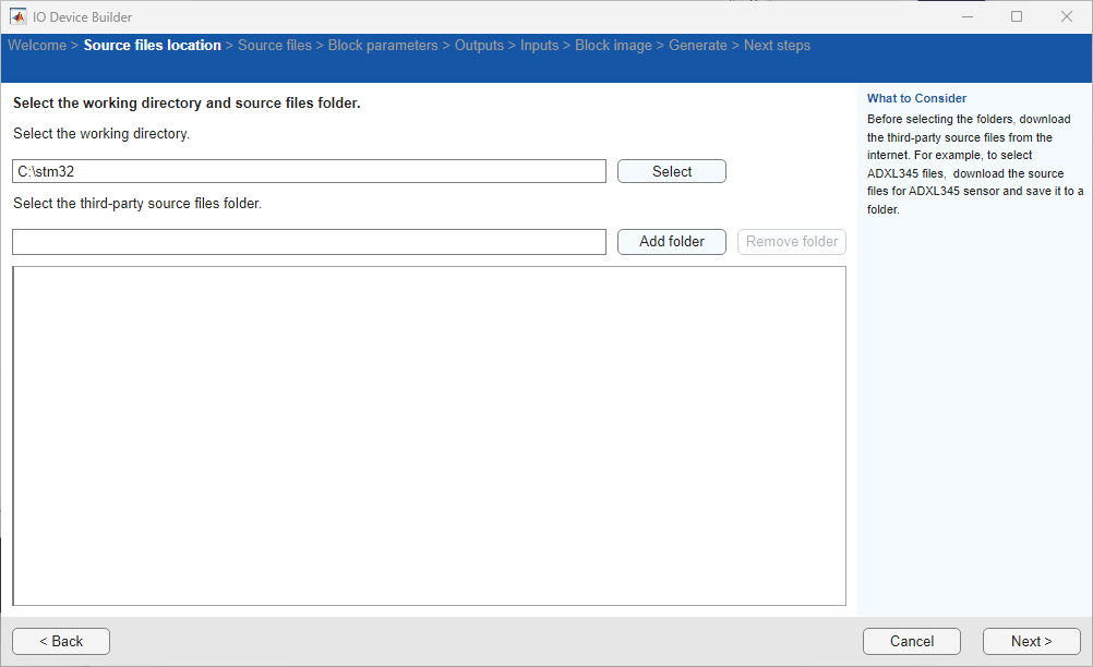
On the Source files location page:
Click Select to select the working directory. The System object™ generated by the app, the corresponding C++ and header files, and the model are located in the working directory.
Click Next to continue.
Note: You do not need to add third-party source files. This example uses STM32CubeMX tool to generate all the required driver files.
Specify Block Parameters
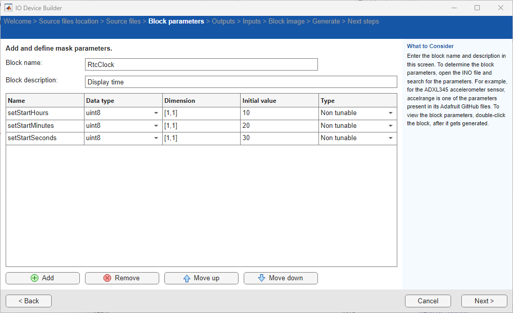
On the Block parameters page:
1. Specify the block name and add block description.
2. Add these parameters and set their type to nontunable and specify their values.
setStartHours - Data type: u
int8,setStartMinutes - Data type:
uint8,setStartSeconds - Data type:
uint8,
3. Click Next to continue.
Select Outputs for the Block
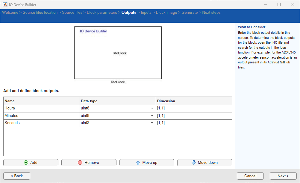
On the Outputs page:
Add the
Hours, Minutes, and Secondsand set their data type touint8and dimension to[1,1].Click Next to continue.
Select Inputs for the Block
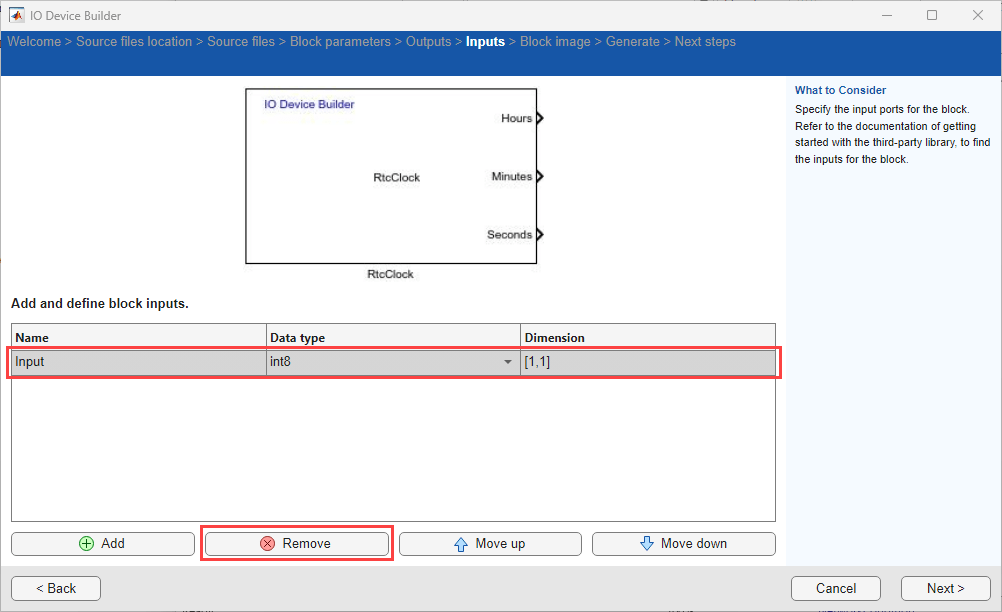
On the Inputs page:
Remove any input ports added to the block.
Click Next to continue.
Preview Block
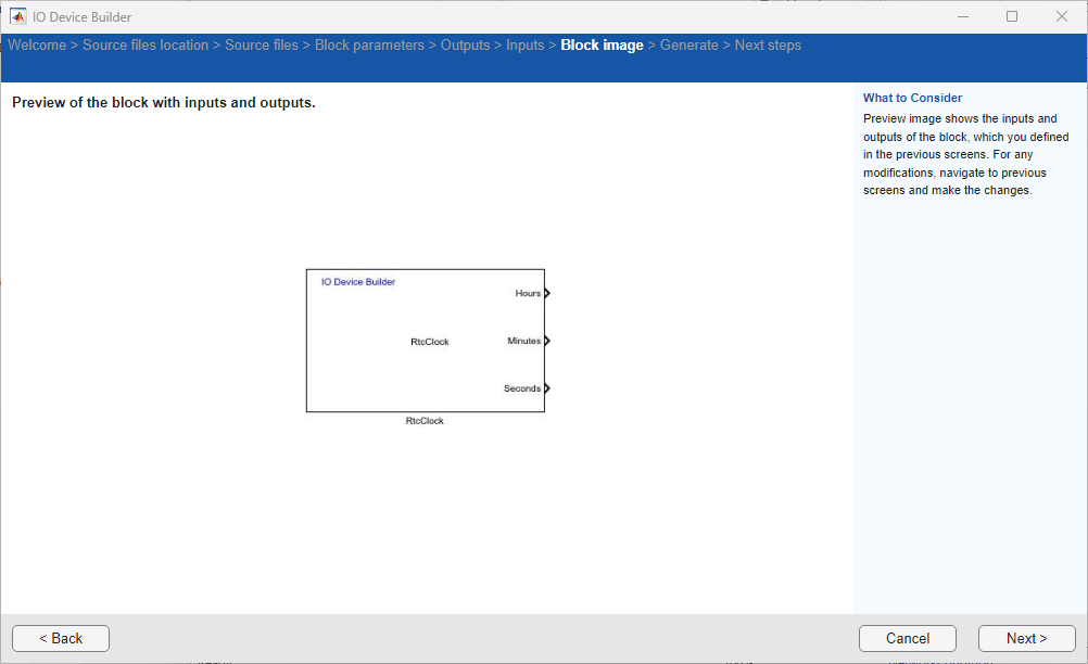
On the Block image page, view a preview of the block with the added output ports. Click Next to continue.
Generate System Object Files
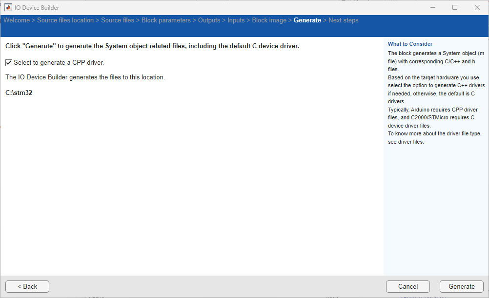
The app displays the location of the System object file on the Generate page. Choose the Select to generate a C++ driver option, if you want to generate a C++ file.
Click Generate to generate the System object files.
Next Steps
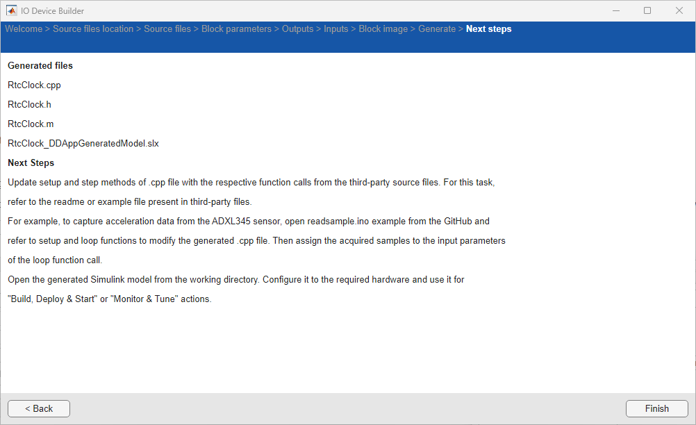
The app displays the names of the generated files and the next steps on the Next Steps page.
Click Finish on this page to complete the process. The generated 'c++' file opens automatically.
1. The generated .cpp file opens automatically. Modify the generated .cpp file by referring to the driver file as shown below.
#include "D:\Projects\RTCDemo\rtcClock.h"   //App generated header. Do not modify.

#include "main.h"
extern RTC_HandleTypeDef hrtc;
RTC_DateTypeDef gDate;
RTC_TimeTypeDef gTime;

void set_time (uint8_T setStartHours,uint8_T setStartMinutes,uint8_T setStartSeconds)
{
    RTC_TimeTypeDef sTime;
    RTC_DateTypeDef sDate;
    sTime.Hours = setStartHours; // set hours
    sTime.Minutes = setStartMinutes; // set minutes
    sTime.Seconds = setStartSeconds; // set seconds
    sTime.DayLightSaving = RTC_DAYLIGHTSAVING_NONE;
    sTime.StoreOperation = RTC_STOREOPERATION_RESET;
    if (HAL_RTC_SetTime(&hrtc, &sTime, RTC_FORMAT_BCD) != HAL_OK)
    {
        // _Error_Handler(__FILE__, __LINE__);
    }
    sDate.WeekDay = 05; //   day
    sDate.Month = 01; //   month
    sDate.Date = 12; // date
    sDate.Year = 24; // year
    if (HAL_RTC_SetDate(&hrtc, &sDate, RTC_FORMAT_BCD) != HAL_OK)
    {
        // _Error_Handler(__FILE__, __LINE__);
    }
    HAL_RTCEx_BKUPWrite(&hrtc, RTC_BKP_DR1, 0x32F2); // backup register
}


// setStartHours uint8 [1,1] Non tunable
// setStartMinutes uint8 [1,1] Non tunable
// setStartSeconds uint8 [1,1] Non tunable

void setupFunctionrtcClock(uint8_T  setStartHours,int size_vector__1,uint8_T  setStartMinutes,int size_vector__2,uint8_T  setStartSeconds,int size_vector__3){
    set_time(setStartHours,setStartMinutes,setStartSeconds);
}

// Hours uint8 [1,1]
// Minutes uint8 [1,1]
// Seconds uint8 [1,1]


void stepFunctionrtcClock(uint8_T * Hours,int size_vector_1,uint8_T * Minutes,int size_vector_2,uint8_T * Seconds,int size_vector_3){
    /* Get the RTC current Time */
    HAL_RTC_GetTime(&hrtc, &gTime, RTC_FORMAT_BIN);
    /* Get the RTC current Date */
    HAL_RTC_GetDate(&hrtc, &gDate, RTC_FORMAT_BIN);
    *Hours=gTime.Hours;
    *Minutes=gTime.Minutes;
    *Seconds=gTime.Seconds;
}
2. Open the generated Simulink model.
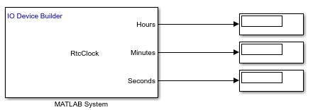
3. Add a MATLAB System block and assign the generated System object file without the .m extension to the block.
4. Add Display blocks to the model and connect them to the output ports.
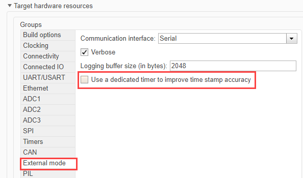
5. In the Simulink model, navigate to Modeling > Model Settings. In the Configuration Parameters dialog box, click Hardware Implementation > Target hardware resource > External mode and then clear the Use a dedicated timer to improve time stamp accuracy option.
6. Click Connectivity and specify the same COM port as the one listed in the device manager for the target.
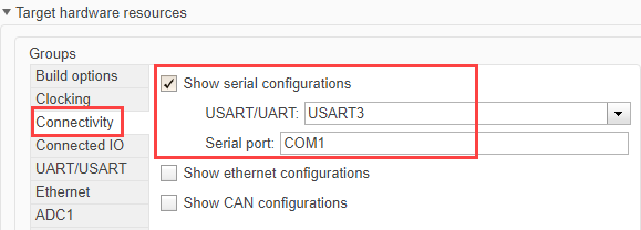
7. Click Apply and OK.
8. Double-click the MATLAB System block and configure the startHours, startMinutes, and startSeconds.
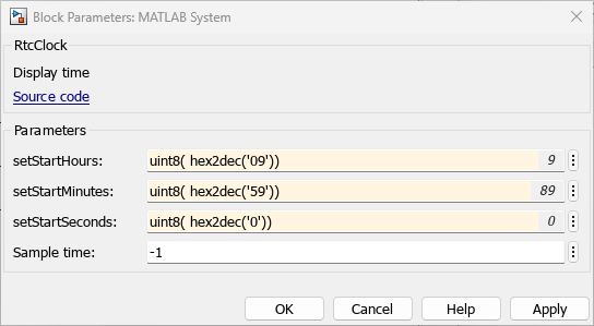
Note: Specify time in the hexadecimal (HEX) format. For example: uint8(hex2dec('18')). Additionally, in STM32CubeMX, the RTC is set to use the 24-hour format by default.
A sample Simulink model is shown here.
Monitor & Tune
Note: Before performing Monitor and Tune action, perform these steps to set the default parameter behavior to tunable.
1. In the Simulink model, press Ctrl+E. The Configuration Parameters dialog box appears.
2. Navigate to Code Generation > Optimization and ensure that Tunable is selected for Default parameter behavior.
To run the model for signal monitoring and parameter tuning, on the Hardware tab, in the Mode section, select Run on board and then click Monitor & Tune to start signal monitoring and parameter tuning.

The Display blocks display the time values.