Generate Sender and Receiver C Interface Code for Component Deployment
This example shows how to generate sender and receiver service functions to send and receive data to and from the target environment by using environment-specific data communication methods. Use data communication methods that match the needs of the target environment. For more information about data communication methods, see Data Communication Methods.
Inspect Model
Open the model.
model = "ComponentDeploymentFcn";
open_system(model);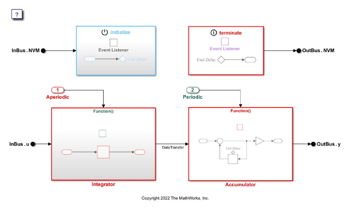
The model contains mixed periodic and aperiodic rates, which require data concurrency safeguards. To enforce data concurrency safeguards, use the Outside Execution or During Execution data communication methods. With these data communication methods, the code generator uses a buffer rather than writing to memory directly. For models that do not require data concurrency safeguards, consider using the Direct Access data communication method, which allows the generated code to read from and write to the target environment memory directly.
Inspect Embedded Coder Dictionary
Inspect the shared Embedded Coder Dictionary and verify the sender and receiver service configuration.
1. Open the Embedded Coder Dictionary. From the C Code tab, under Code Interface, select Embedded Coder Dictionary (Shared).
2. In the Embedded Coder Dictionary, in the left pane, select Service Interfaces. The center pane populates with service interfaces.
3. In the center pane, under Receiver, verify that the ReceiverOutsideExe service interface has the Dictionary Default check box selected.
4. Click the ReceiverOutsideExe row. The right pane populates with information about the service interface. In this case, the service interface uses the Outside Execution data communication method and the function naming rule get_$X_input. The $X token represents the name of the entry-point function that encloses the access function.
5. Under Sender, verify that the SenderOutsideExe row is selected as Dictionary Default and that the service uses the Outside Execution data communication method and the function naming rule set_$X_output.
When you select the Outside Execution data communication method, the generated code applies data concurrency safeguards by using a buffer provided by the target environment. Outside Execution allows communication with the target environment to occur only between task iterations.
Inspect Code Mappings
Inspect the Code Mappings editor and verify that the model root inports and outports map to the default sender and receiver services.
1. From the C Code tab, under Code Interface, select Component Interface. The Code Mappings editor pane opens.
2. In the Code Mappings editor, select the Inports tab. The model contains two Bus Element Inport blocks, InBus.NVM and InBus.u. Verify that, for both inports, the Receiver Service column is set to Dictionary default: ReceiverOutsideExe.
3. From the Outports tab, verify that both of the Bus Element Outport blocks, OutBus.NVM and OutBus.y, use the Dictionary default: SenderOutsideExe sender service.
Generate Code
Verify that the generated code uses the Outside Execution communication method.
1. Generate the code.
slbuild(model);
### Searching for referenced models in model 'ComponentDeploymentFcn'.
### Total of 1 models to build.
### Starting build procedure for: ComponentDeploymentFcn
### Successful completion of code generation for: ComponentDeploymentFcn

Build Summary

Top model targets:

Model                   Build Reason                                         Status           Build Duration
============================================================================================================
ComponentDeploymentFcn  Information cache folder or artifacts were missing.  Code generated.  0h 0m 8.8124s

1 of 1 models built (0 models already up to date)
Build duration: 0h 0m 9.2887s
2. Inspect the services.h file.
/* receiver services */
extern const real_T * get_CD_integrator_input(void);
extern const real_T * get_CD_initialize_input(void);

/* sender services */
extern real_T * set_CD_accumulator_output(void);
extern real_T * set_CD_terminate_output(void);
With the Outside Execution data communication method, the code generator expects the target environment to provide a buffer for data communication. The sender and receiver function services do not need a pointer to a generated buffer; each service function takes no arguments.
In the service function names, the code generator replaces the $X token with the name of the enclosing entry-point function, CD_accumulator.
3. Inspect the CD_accumulator function in ComponentDeploymentFcn.c.
void CD_accumulator(void)
{
  const real_T *tmpIrvIRead;
  int32_T i;
  tmpIrvIRead = get_CD_accumulator_DataTransfer();
  for (i = 0; i < 10; i++) {
    CD_sig.delay[i] += tmpIrvIRead[i];
    (set_CD_accumulator_output())[i] = CD_param.tunable_gain * CD_sig.delay[i];
  }
}
With the Outside Execution data communication method, the generated code calls the sender service inside the for loop. The sender service populates the provided buffer or gives access to that buffer for the entry-point function to populate. The target environment reads the buffer after the entry-point function executes and uses it for the next task iteration.
Modify Code Mappings and Regenerate Code
1. Open the Code Mappings editor and navigate to the Inports tab. For each inport, change the Receiver Service column from Dictionary default: ReceiverOutsideExe to ReceiverDuringExe. When you select this service, the sender services use the During Execution data communication method. When using this data communication method, the code generator still enforces data concurrency safeguards by using a buffer, but generates the buffer in the code rather than expecting the buffer to be provided by the target environment. The During Execution data communication method allows services to transfer data during a task iteration.
2. Navigate to the Outports tab and map each outport to SenderDuringExe.
3. Generate the code.
slbuild(model);
### Searching for referenced models in model 'ComponentDeploymentFcn'.
### Total of 1 models to build.
### Starting build procedure for: ComponentDeploymentFcn
### Generated code for 'ComponentDeploymentFcn' is up to date because no structural, parameter or code replacement library changes were found.
### Successful completion of code generation for: ComponentDeploymentFcn

Build Summary

0 of 1 models built (1 models already up to date)
Build duration: 0h 0m 3.4267s
4. Inspect the CD_accumulator function in ComponentDeploymentFcn.c.
void CD_accumulator(void)
{
  real_T OutBus_y[10];
  const real_T *tmpIrvIRead;
  int32_T i;
  tmpIrvIRead = get_CD_accumulator_DataTransfer();
  for (i = 0; i < 10; i++) {
    CD_sig.delay[i] += tmpIrvIRead[i];
    OutBus_y[i] = CD_param.tunable_gain * CD_sig.delay[i];
  }

  set_CD_accumulator_output(&OutBus_y[0]);
}
With the During Execution data communication method, the generated code includes the same sender and receiver services as before, but these services can now execute during task iterations. The code generator generates a data buffer, OutBus_y, in the code. The generated code populates this buffer inside the for loop, then sends this buffer through the sender service after the for loop. This means that the sender service is called only once during the function execution.
5. Inspect the services.h file.
/* receiver services */
extern void get_CD_integrator_input(real_T *const rty_InBus_u_value);
extern void get_CD_initialize_input(real_T *const rty_InBus_NVM_value);

/* sender services */
extern void set_CD_accumulator_output(const real_T *const rtu_OutBus_y);
extern void set_CD_terminate_output(const real_T *const rtu_OutBus_NVM);
The generated sender and receiver services each take a pointer to a buffer in the generated code as an argument.