Fixed-Point Conversion Using Fixed-Point Tool and Derived Range Analysis
This example shows how to use derived range analysis to collect ranges that then can be used by the Fixed-Point Tool to propose fixed-point scaling.
Overview
The Fixed-Point Tool can collect range data either by simulating the model and logging range information or by running derived range analysis. Range information obtained from simulation is completely dependent on the input to the simulation. Accurate range information can be obtained only if the inputs exercise the system over its full operating range. Unlike range collection using simulation logging, derived range analysis does not depend on sample inputs. Instead it uses formal methods to generate range information.
The benefits of derived range analysis over simulation logging are:
Accurate results regardless of quality of input data
Faster analysis times
Open and Inspect Model
Open the ex_fxpdemo_corner_detection model.
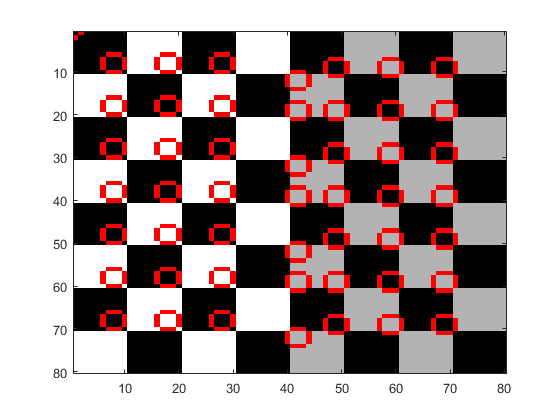
This model implements a corner detection algorithm based on the Harris corner detection method. The top level of the model includes blocks required to run the simulation. Note that the input to the simulation is a checker board image and the output is a 2 by n workspace matrix variable, cornerMarks, that contains locations of all found corners. The Corner Detector subsystem implements the algorithm. Within the Corner Detector subsystem, the Sobel Edge block applies Sobel operator to the input data, and the Corner Metric subsystem calculates the Harris corner metric. This example focuses on analyzing ranges of the Corner Metric subsystem using the Fixed-Point Tool.
Note: Design ranges on inputs to the Corner Metric subsystem have been explicitly specified by the user prior to running the analysis. Those design ranges can be obtained either from running derived range analysis, simulating the model with logging on the system, or inferred from the model.

Simulate Model
Some blocks inside the Corner Metric subsystem have fixed-point types manually specified. However, some of the types were chosen poorly, and the model fails to detect corners correctly. Simulate the model by clicking the Simulate button. Observe that numerous overflows occur and that most of the corners are not marked.
In the Fixed-Point Tool, in the Visualization of Simulation Data pane, overflow markers indicate the blocks in the model that overflowed during simulation. The Fixed-Point Tool shows overflows occurred in the Gaussian Filter Accumulators.
Prepare Model For Conversion
To open the Fixed-Point Tool, right click on the Corner Metric subsystem and select Fixed-Point Tool.
Run Derived Range Analysis
The Fixed-Point Tool derives ranges by analyzing the generated code. Fixed-point data types generate more code and can make it harder for the analysis to derive accurate ranges. To improve the accuracy of the results, derive ranges of models using double-precision data types.
In the Fixed-Point Tool, in the Collect Ranges section of the tool-strip, click the Derived Ranges button to specify the range collection method. To begin the range analysis click the Collect Ranges button. This action overrides the data types in the model with double-precision types before performing the analysis to improve the accuracy of the results. After the analysis finishes, the Fixed-Point Tool displays collected range information.
Propose Fixed-Point Data Types
Range information obtained from derived range analysis can be used by the Fixed-Point Tool to propose fixed-point data types for blocks in the model. This can be done by clicking Propose Data Types button in the Fixed-Point Tool.
Apply Proposed Data Types
To apply the proposed data types, click the Apply Data Types button. By default, the Fixed-Point Tool applies all of the proposed data types. To apply a subset of the proposals, use the Accept check box to specify the proposals that you want to apply.
Verify Proposed Data Types
Proposed types should handle all possible inputs correctly. Set the model to use the newly applied types, simulate the model, and observe that all of the corners are now detected.
Note: Applying proposed data types updates the data type visualization and removes the corresponding overflow indicators

You can also select a web site from the following list:
Americas
- América Latina (Español)
- Canada (English)
- United States (English)
Europe
- Belgium (English)
- Denmark (English)
- Deutschland (Deutsch)
- España (Español)
- Finland (English)
- France (Français)
- Ireland (English)
- Italia (Italiano)
- Luxembourg (English)
- Netherlands (English)
- Norway (English)
- Österreich (Deutsch)
- Portugal (English)
- Sweden (English)
- Switzerland
- United Kingdom (English)