Vehicle HVAC System Control Using Fuzzy Logic
This example shows a fuzzy logic-based automatic control system for a vehicle HVAC system. The fuzzy controller uses two fuzzy systems:
The first fuzzy inference system (FIS) calculates climate control setpoints to maintain a desired cabin temperature. The control setpoints include a desired airflow level and the on/off state of an AC system.
The second fuzzy system uses a fuzzy PID controller to regulate a heating system for maintaining the desired cabin temperature.
Vehicle HVAC System
The vehicle HVAC system is implemented using Simscape™ blocks.
Load the model.
model = "FuzzyVehicleClimateControl";
open_system(model)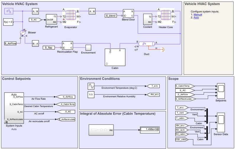
The vehicle HVAC model is adapted from the Vehicle HVAC System (Simscape) example, which models moist air flow in a vehicle heating, ventilation, and air conditioning system.
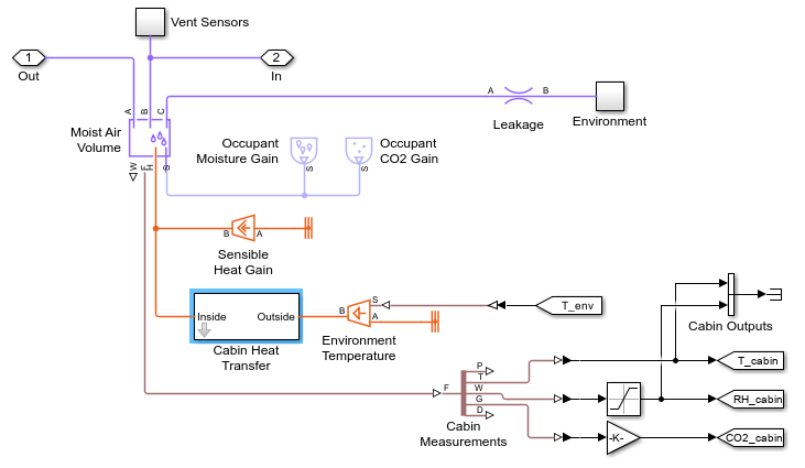
The following figure shows the vehicle cabin model, which is represented as a volume of moist air exchanging heat with the external environment. The moist air flows through a recirculation flap, a blower, an evaporator, a blend door, and a heater before returning to the cabin.
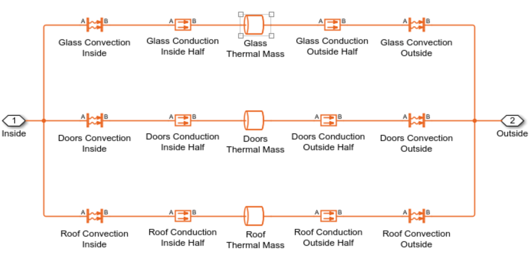
This figure shows the cabin heat transfer model, which includes heat transfer models for various vehicle components.
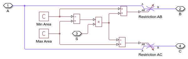
The recirculation flap model, as shown in the following figure, selects flow intake from the cabin or from the external environment.
The blender door, as shown in the following figure, diverts flow around the heater to control the temperature.

In this example, you implement the blend door controller using a Fuzzy PID Controller block, as shown in the following figure.
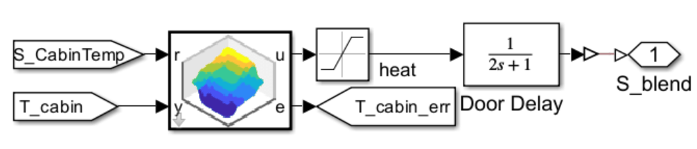
The fuzzy PID controller block is configured as a continuous-time controller.
The following scaling parameters and the filter coefficients for the controller are tuned as described in Implement Fuzzy PID Controller in Simulink example. The scaling parameters are computed based on a cabin temperature setpoint of 20 degrees Celsius and outside temperature of 30 degrees Celsius.
Kp = 10;
Ki = 1;
Kd = 5;
Ce = 1;
Cd = Ce*(Kp-sqrt(Kp^2-4*Ki*Kd))/2/Ki;
C0 = Ki/Ce;
C1 = Kd/Cd;
The FIS used in this block is similar to the fuzzy system used in Fuzzy Logic Control for House Heating System example. The fuzzy PID controller outperforms the PID controller with the varying outside temperature condition in terms of integral of absolute temperature error values.
The heater core and the evaporator are custom components based on the Simscape Foundation Moist Air library and are basic implementations of heat exchangers using the e-NTU method.
Climate Control
In the model, you can specify climate control setpoints in two modes: manual or auto system inputs.
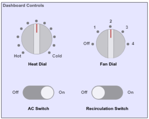
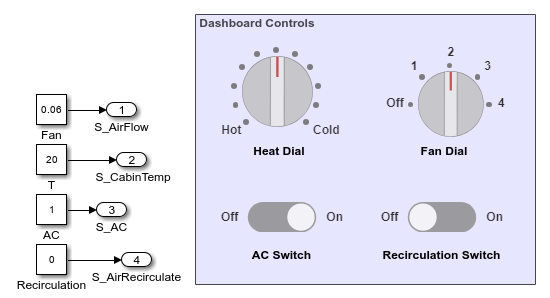
For manual system inputs, you adjust the control settings at run time using dashboard controls. The manual controls are in the System Inputs/Manual subsystem.
When using automatic system inputs, a FIS generates a suitable airflow level with or without AC for maintaining a comfortable temperature in the cabin. The air circulation is switched off for this control mode.
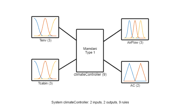
The fuzzy system uses the environment and cabin temperatures as inputs to generate the control setpoints.

Fuzzy Inference System
The fuzzy system uses a rule base to create the climate control setpoints.
The rule base includes these operating rules:
The airflow is always kept on to keep the CO2 level to a safe limit.
The airflow level is mostly kept low for low fan power consumption. Higher airflow levels are used for cold air circulation when the AC is on. The rule set also uses a higher airflow level (without AC) when both the outside and cabin temperatures are similar and comfortable.
AC is switched on to maintain a comfortable temperature in the cabin when the outside temperature is high.
controller = createFISController;
plotfis(controller)
controller.Rules
ans =
  1×9 fisrule array with properties:

    Description
    Antecedent
    Consequent
    Weight
    Connection

  Details:
                          Description
         ______________________________________________

    1    "Tenv==L & Tcabin==L => AirFlow=L, AC=Off (1)"
    2    "Tenv==M & Tcabin==L => AirFlow=L, AC=Off (1)"
    3    "Tenv==H & Tcabin==L => AirFlow=L, AC=Off (1)"
    4    "Tenv==L & Tcabin==M => AirFlow=L, AC=Off (1)"
    5    "Tenv==M & Tcabin==M => AirFlow=M, AC=Off (1)"
    6    "Tenv==H & Tcabin==M => AirFlow=H, AC=On (1)"
    7    "Tenv==L & Tcabin==H => AirFlow=L, AC=Off (1)"
    8    "Tenv==M & Tcabin==H => AirFlow=L, AC=Off (1)"
    9    "Tenv==H & Tcabin==H => AirFlow=M, AC=On (1)"
Here, L, M, and H stand for low, medium, and high, respectively.
The rule base produces the following input-output control surfaces.
h = figure(Name="Fuzzy Control Surface");
subplot(1,2,1)
options = gensurfOptions(OutputIndex=1);
gensurf(controller,options)
subplot(1,2,2)
options.OutputIndex = 2;
gensurf(controller,options)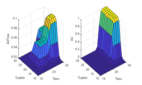
Simulation Results
Use these environment conditions for the simulations in this example:
Outside air temperature varies sinusoidally between 10 and 30 degrees Celsius in 24 hours.
Relative humidity is 0.5.
Manual Inputs
To enable manual simulation, click the Manual hyperlink in the model. Alternatively, you can enable manual operation using the following command.
set_param(model + "/System Inputs","OverrideUsingVariant","Manual")
Use these dashboard settings for a manual input simulation:
Air recirculation is switched off.
AC is switched on.
Heat and fan dials are set to medium levels.
Simulate the model.
sim(model);
View the control setpoints.
open_system(model + "/Setpoints")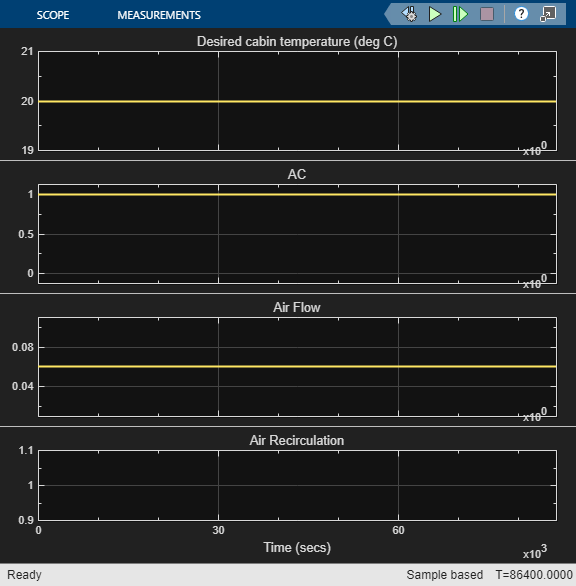
View the cabin sensor data.
open_system(model + "/Sensor Data")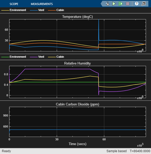
The simulation results show that the cabin temperature is maintained throughout the day close to the set level with an error level (integral of absolute error) of 1.856e5.
The relative humidity of the cabin decreases with heating at low (outside) temperature. The CO2 content remains similar due to a fixed level of airflow (without air recirculation).
Auto Inputs
To enable automatic simulation, click the Auto hyperlink in the model. Alternatively, you can enable manual operation using the following command.
set_param(model + "/System Inputs","OverrideUsingVariant","Auto")
Simulate the model.
sim(model);
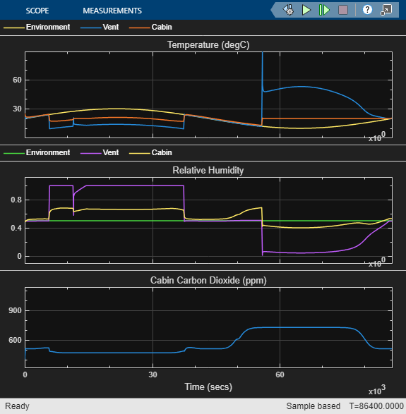

In this case:
The cabin temperature is maintained with a smaller error level of 1.106e5 as compared to the manual input mode.
The CO2 content varies due to different airflow settings.
Next Steps
The current control strategy does not use air recirculation for enhanced cooling due to a risk of increasing CO2 in the cabin. However, air recirculation can be used if a vehicle is equipped with a CO2 sensor or using a timer-based control strategy to keep the air recirculation on for a specific duration to keep the CO2 level to a safe limit.
As an example, you can add another FIS, CO2Controller as follows to keep the CO2 level to a safe limit.
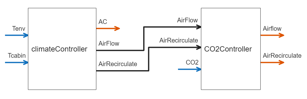
An example rule set is shown below for CO2Controller FIS.
    1    "AirFlow==L & AirRecirculation==Off & CO2~=H => Airflow=L, AirRecirculation=Off (1)"
    2    "AirFlow==M & AirRecirculation==Off & CO2~=H => Airflow=M, AirRecirculation=Off (1)"
    3    "AirFlow==H & AirRecirculation==Off & CO2~=H => Airflow=H, AirRecirculation=Off (1)"
    4    "AirFlow==L & AirRecirculation==On & CO2~=H => Airflow=L, AirRecirculation=On (1)"
    5    "AirFlow==M & AirRecirculation==On & CO2~=H => Airflow=M, AirRecirculation=On (1)"
    6    "AirFlow==H & AirRecirculation==On & CO2~=H => Airflow=H, AirRecirculation=On (1)"
    7    "CO2==H => Airflow=H, AirRecirculation=Off (1)"
Here, CO2Controller increases airflow and switch off air recirculation when cabin CO2 level is high.
You can also add a humidity controller if a vehicle is equipped with a sensor for relative humidity measurement.
Local Functions
function controller = createFISController
% Create a FIS for vehicle climate control.

% Construct FIS
controller = mamfis(Name="climateController");
% Input 1
controller = addInput(controller,[10 30],Name="Tenv");
controller = addMF(controller,"Tenv","zmf",[10 18], ...
    Name="L",VariableType="input");
controller = addMF(controller,"Tenv","gaussmf",[2 20], ...
    Name="M",VariableType="input");
controller = addMF(controller,"Tenv","smf",[22 30], ...
    Name="H",VariableType="input");
% Input 2
controller = addInput(controller,[10 30],Name="Tcabin");
controller = addMF(controller,"Tcabin","zmf",[10 18], ...
    Name="L",VariableType="input");
controller = addMF(controller,"Tcabin","gaussmf",[2 20], ...
    Name="M",VariableType="input");
controller = addMF(controller,"Tcabin","smf",[22 30], ...
    Name="H",VariableType="input");
% Output 1
controller = addOutput(controller,[-0.02 0.14],Name="AirFlow");
controller = addMF(controller,"AirFlow","gaussmf",[0.01 0.02], ...
    Name="L",VariableType="output");
controller = addMF(controller,"AirFlow","gaussmf",[0.01 0.06], ...
    Name="M",VariableType="output");
controller = addMF(controller,"AirFlow","gaussmf",[0.01 0.1], ...
    Name="H",VariableType="output");
% Output 2
controller = addOutput(controller,[-0.5 1.5],Name="AC");
controller = addMF(controller,"AC","trimf",[-0.5 0 0.5], ...
    Name="Off",VariableType="output");
controller = addMF(controller,"AC","trimf",[0.5 1 1.5], ...
    Name="On",VariableType="output");
% Rules
controller = addRule(controller, ...
    [1 1 1 1 1 1; ...
    2 1 1 1 1 1; ...
    3 1 1 1 1 1; ...
    1 2 1 1 1 1; ...
    2 2 2 1 1 1; ...
    3 2 3 2 1 1; ...
    1 3 1 1 1 1; ...
    2 3 1 1 1 1; ...
    3 3 2 2 1 1]);
end
See Also
Fuzzy PID Controller | Fuzzy Logic Controller