Set Up Microchip FPGA and SoC Devices
R2026bYou can use the Hardware Setup add-on to configure your target Microchip hardware board for the hardware-software co-design workflow. To set up the board, you load the MathWorks® firmware image onto an SD card, then use the Hardware Setup Add-On to configure the board, establish an Ethernet connection to the hardware, and set the hardware connections. For more information, see Hardware-Software Co-Design Workflow for SoC Platforms.
Prerequisites
Before using the Hardware Setup add-on, install the HDL Coder™ Support Package for Microchip FPGA and SoC Devices. See Download and Install HDL Coder Support Package for Microchip FPGA and SoC Devices.
Additionally, you must have this software:
For Windows machines, install Win32DiskImager.
For Linux machines, install bmaptool.
Open the Hardware Setup tool
You can launch the Hardware Setup add-on by using the Add-Ons panel, the
hdlHardwareSetup function, or the HDL Coder app.
Using Add-Ons Panel
You can start the Hardware Setup add-on by opening the Add-Ons panel. Select Add-Ons > Manage Add-Ons.
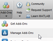
To launch the Hardware Setup add-on, point to the HDL Coder Support Package
for Microchip FPGA and SoC Devices and click the Settings button  .
.
Using hdlHardwareSetup Function
You can also start the Hardware Setup add-on by using hdlHardwareSetup function. Enter this command in MATLAB® command window:
hdlHardwareSetup
Using HDL Coder App
Alternatively, you can start the Hardware Setup add-on by using the HDL Coder app in Simulink®. To open the Hardware Setup from the Simulink Toolstrip,
In Simulink, click the Apps tab and select HDL Coder.
In the HDL Code tab, in the Output section, set the drop-down button to IP Core.
Click the Settings button to open the HDL Code Generation > Target tab of Configuration Parameters dialog box. Set Target Platform to your target microchip board. Click OK.
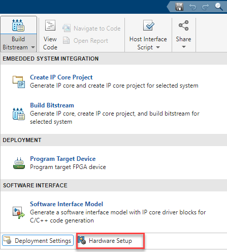
In the HDL Code tab, click Build Bitstream>Hardware Setup.
Select Hardware Board
In this step, you choose the HDL workflows and board‑specific settings of your target hardware. You can configure the hardware board for HDL workflows such as FPGA verification and debug or IP core generation. The hardware setup steps vary based on the selected HDL workflow and target board.
FPGA Vendor: Select the FPGA manufacturer for the target device. Set the FPGA Vendor to
Microchip.Workflow: Specify the HDL workflow you want to use.
Family: Specify the FPGA device family.
Hardware Board: Choose the target hardware board from the list or custom hardware board.
Add‑On Card: Choose an add‑on card supported with the selected hardware board.
For more information on the supported hardware, see Supported EDA Tools and Hardware.

Select Interface
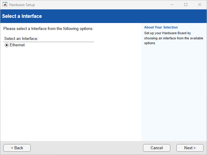
Select an interface to configure your hardware board. You can set an interface to Ethernet. For the full list of supported boards and interfaces, see Supported EDA Tools and Hardware.
Download Required Third-Party Tools
This step appears only when you select the Hardware Board to
PolarFire SoC Icicle Kit.
You can automatically or manually download third-party tools for your board.

If you select Automatic, the wizard downloads the required third-party tools from the internet to your host computer, which must have internet connectivity.

After the download completes, the third-party tools are available in the folder
support_package_installation_folder/downloads/,
where support_package_installation_folder is the folder
where the HDL Coder Support Package for Microchip FPGA and SoC Devices is installed. To get to the root folder of the
support packages, use the matlabshared.supportpkg.getSupportPackageRoot function. Extract the
microchip_linuxbinaries folder.
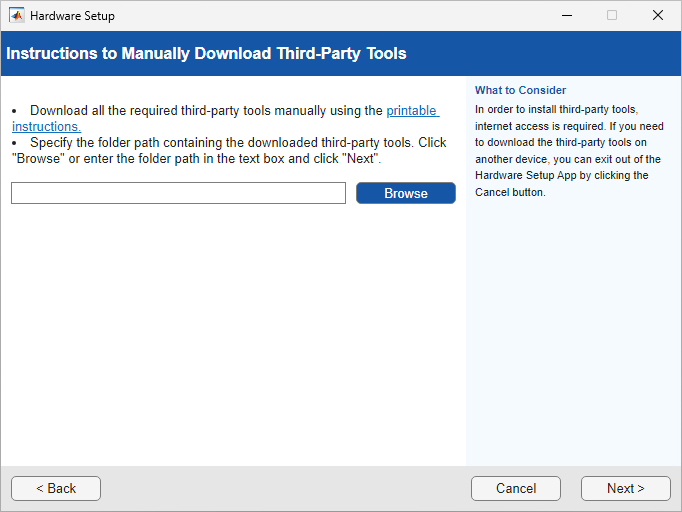
For host computers that do not have internet access, select Manual to manually download the third-party tools. The wizard provides step-by-step instructions for downloading the required third-party tools. Use another computer with internet access to download these tools and then transfer them to your host computer. After transferring the required third-party tools to the host computer, specify the folder path that contains the third-party tools and click Next.
Ethernet Setup Steps
This step appears for the FPGA verification and debug workflow when you select the
Hardware Board to PolarFire Evaluation
Kit, RTG4 FPGA, or
.SmartFusion2 SoC FPGA Advanced Development
Kit.
Follow these steps to set up your hardware board with the ethernet interface:
Turn off power switch on the board.
Connect the AC power cord to the power plug, and plug the power supply adapter cable into the hardware board.
Use the crossover Ethernet cable to connect the Ethernet connector on the hardware board directly to the Ethernet adapter on your host computer.
Use the JTAG download cable to connect the hardware board to the host computer.
Make sure that the jumpers on the hardware board are in the factory default position.
Turn the power switch of the hardware board on.
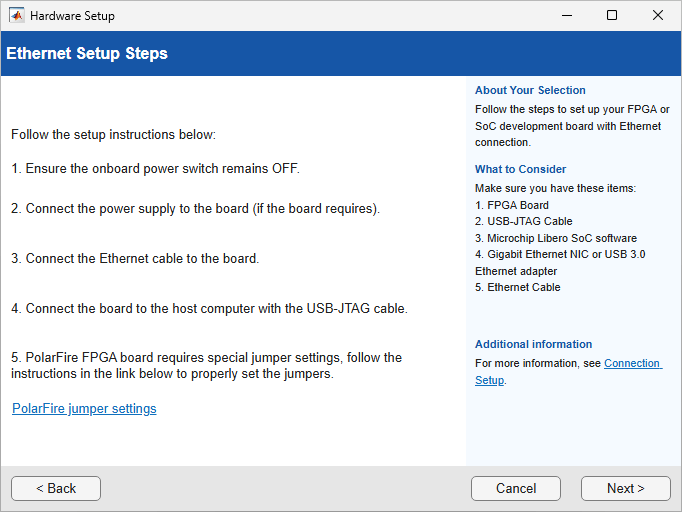
After setting up the connection, click Next.
Configure Network Card on Host Computer
This step appears when you select the Hardware Board to
PolarFire Evaluation
                    Kit
, RTG4
FPGA, or .SmartFusion2 SoC FPGA Advanced Development
Kit.
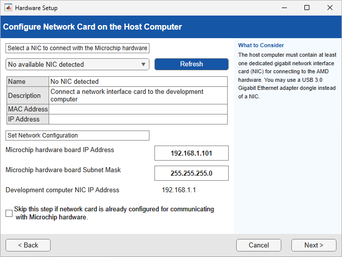
In this step, you configure the host computer so that it can communicate with the hardware board. You must have a dedicated Gigabit Ethernet NIC for the hardware board, with an Ethernet cable connecting the card to your hardware board. If you also want simultaneous internet access and you do not have a wireless connection, your host computer requires a second Ethernet NIC. In this case, consider using a USB 3.0 Gigabit Ethernet adapter dongle.
Select the network interface card (NIC) that you want to connect with the hardware. If you have already configured the NIC, select Skip this step if your network card is already configured for communicating with Microchip hardware. If you do not see your NIC, click Refresh.
The list displays the connected network interface cards detected on your computer. The menu options note each NIC as
(In Use)or(Available). When the NIC is connected to a device and has an assigned IP, the installer marks the NIC as(In Use).If all the NICs listed are in use, free up a NIC for use with the hardware, and then click Refresh.
If the NIC list is empty, it is possible that the VMWare software, if present, is interfering with NIC detection. To get a list of NICs on your computer, remove the VMWare. Alternatively, check if the missing NIC is disabled in the control panel. If it is disabled, enable it.
Optionally, specify an IP address for your board. Click Next. The software configures the NIC.
Verify Connection of Hardware Board
This step appears when you select the Hardware Board to
PolarFire Evaluation Kit, RTG4
FPGA, or .SmartFusion2 SoC FPGA Advanced Development
Kit.
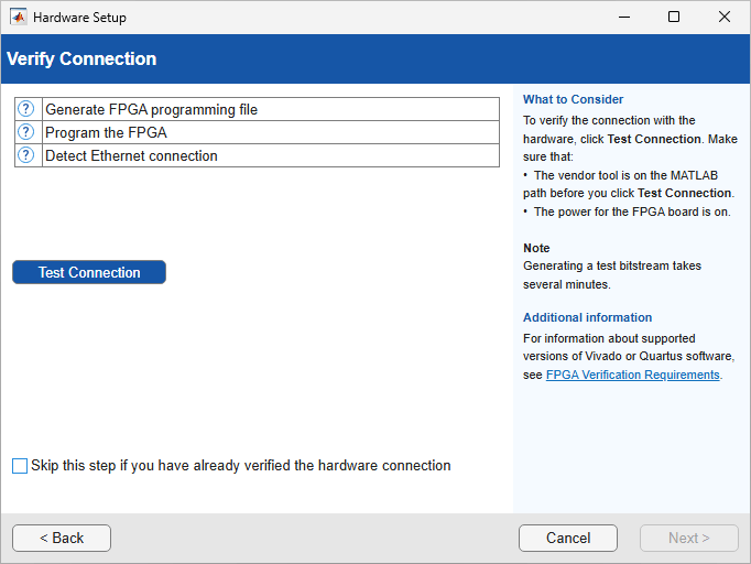
To verify the connection between the hardware board and your computer, click the Test connection button and then click Next. After you verify the connection, you see a message that the hardware setup is complete.
You can skip this step if the connections to your board and development computer is already verified.
Download Linux Image
This step appears only when you select the Hardware Board to
PolarFire SoC Icicle Kit.
This step provides instructions to download the Linux image to SD card. To download Linux image to SD card, use Win32DiskImager or bmaptool.

After copying the Linux image to the SD card, click Finish.
Open Examples
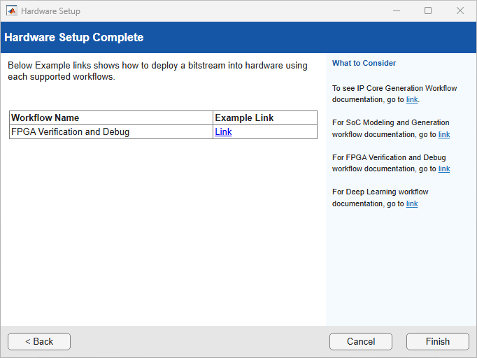
When the Hardware Setup completes, you can open the examples to get familiar with the product and its features. Click Open Example button to launch example in MATLAB which shows how to deploy a bitstream into the hardware.
See Also
Topics
- Download and Install HDL Coder Support Package for Microchip FPGA and SoC Devices
- Supported EDA Tools and Hardware

