Pilot-Operated Check Valve (IL)
Check valve with pilot pressure control in an isothermal liquid system

Libraries:
Simscape /
Fluids /
Isothermal Liquid /
Valves & Orifices /
Directional Control Valves
Description
The Pilot-Operated Check Valve (IL) block models a flow-control valve that allows variable-direction flow based on the pilot-line pressure. The free flow direction is from port A to port B and the valve opens when the control pressure rises above the cracking pressure. When the control pressure exceeds the value of the Cracking pressure differential parameter or the value of the first element of the Control pressure vector or Reference pressure differential vector parameters, the poppet moves to allow flow in either direction. There is no mass flow at port X or between port X and ports A and B.
When the Pilot pressure direction parameter is
Pilot-to-open, the control pressure,
pcontrol is
where:
ppilot is the control pilot pressure differential.
When the Opening pilot pressure specification parameter is
Pressure difference of port X relative to
									port A
, ppilot is the pressure differential between port X and port A.When Opening pilot pressure specification is
Gauge pressure at port X, ppilot is the pressure difference between port X and atmospheric pressure.
kp is the value of the Pilot ratio parameter, which is the ratio of the area at port X to the area at port A,
pA – pB is the pressure differential over the valve.
When the Pilot pressure direction parameter is
Pilot-to-close, the control pressure is
where ppilot = pX - pB.
Spool Configuration
When the Pilot pressure direction parameter is
Pilot-to-open, you can configure the spool and poppet
as either rigidly connected or disconnected. When the Spool
configuration parameter is Disconnected pilot spool and
poppet, the relative pressure at port X must
be positive. If the measured pilot pressure is negative, the control pressure is
based only on the pressure differential between ports A and
B. When the Spool configuration
parameter is Rigidly connected pilot spool and poppet,
the pilot pressure is the measured pressure differential according to the opening
specification.
When the Pilot pressure direction parameter is
Pilot-to-close, the pilot spool and poppet are
disconnected. The relative pressure at port X must be positive.
If the measured pilot pressure is negative, the control pressure is based only on
the pressure differential between ports A and
B.
Area vs. Pressure Opening Parameterizations
When Opening parameterization is Linear - Area vs.
pressure or Tabulated data - Area vs.
pressure, the mass flow rate through the valve is
where:
Cd is the value of the Discharge coefficient parameter.
Avalve is the instantaneous valve open area.
Aport is the value of the Cross-sectional area at ports A and B parameter.
is the average fluid density.
Δp is the valve pressure difference, pA – pB.
The critical pressure difference, Δpcrit, is the pressure differential associated with the Critical Reynolds number, Recrit, the flow regime transition point between laminar and turbulent flow,
The pressure loss is the pressure reduction in the valve due to a decrease in area. PRloss is
The pressure recovery is the positive pressure change in the valve due to an increase in area. If you do not want to capture this increase in pressure, clear the Pressure recovery check box. In this case, PRloss is 1.
When Opening parameterization is Linear -
Area vs. pressure, the valve area is
where the normalized pressure, , is
When the valve is in a near-open or near-closed position, you can maintain numerical robustness in your simulation by adjusting the Smoothing factor parameter. If the Smoothing factor parameter is nonzero, the block smoothly saturates the control pressure between pmax and pcracking. For more information, see Numerical Smoothing.
When Opening parameterization is Tabulated
data - Area vs. pressure, the block interpolates the area of
the valve as
where:
pcontrol,TLU is the Control pressure vector parameter
Avalve,TLU is the Opening area vector parameter.
The area of the valve saturates between the first and last element of the Opening area vector parameter. The first element of the Control pressure vector parameter corresponds to the cracking pressure differential.
Volumetric Flow Rate vs. Pressure Parameterization
When Opening parameterization is Tabulated data
- Volumetric flow rate vs. pressure, the mass flow rate is
and
where:
Δpref,TLU is the Reference pressure differential vector parameter.
ref,TLU is the Reference volumetric flow rate vector parameter.
The value of K saturates between the values and , which means that the first elements of the Reference pressure differential vector and Reference volumetric flow rate vector parameters correspond to the leakage mass flow rate and the last elements correspond to the maximum mass flow rate.
Opening Dynamics
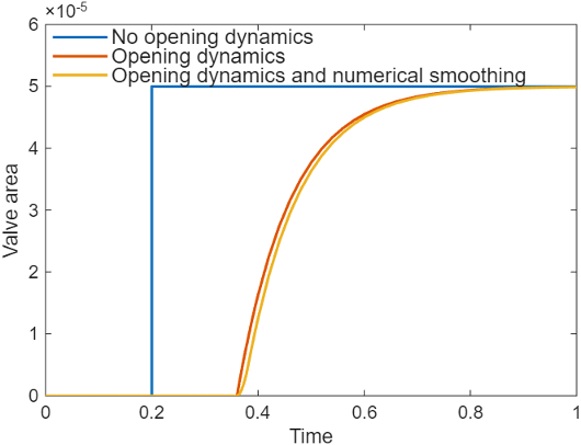
When you select Opening dynamics, the block applies a first-order filter to the valve area based on the Opening time constant parameter, τ. The valve area, Avalve, becomes the dynamic area, Adyn,
When you select Opening dynamics, the valve does not respond to changes instantaneously. This figure shows an example valve area in response to a step in the valve input pressure with and without opening dynamics:
When you clear Opening dynamics, the valve area mirrors the step change in the pressure at the input.
When you select Opening dynamics and set Opening time constant to
0.1 s, the valve area asymptotically approaches its limit.
Specifying a nonzero value for the Smoothing factor parameter provides additional numerical stability when the valve area is changing and in the near-closed or near-open position. For more information, see Numerical Smoothing.
Mass Conservation
Mass is conserved through the valve,
Examples
This example shows a test rig for the Pilot-Operated Check Valve (IL) block. The valve connects to three ideal pressure sources, two of which create the pressure differential across the main flow line, while the third applies pressure to the pilot port X. This pressure allows flow through the valve even if the main pressure differential is negative.
Model

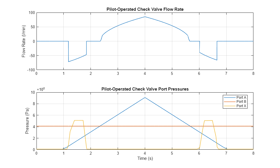
Simulation Results from Scopes

Simulation Results from Simscape Logging
The plots below show the behavior of the pilot-operated check valve under various pressure conditions. The valve opens when the control pressure is larger than the cracking pressure differential. The control pressure is 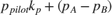 , where
  is the pilot pressure determined using the pressure at port X and
  is the pilot ratio. If the pilot pressure is sufficiently large, the valve opens even if the pressure differential
  is negative. With
  and the valve opened, fluid flows from port B to port A.