Pipe Bend (G)
Libraries:
Simscape /
Fluids /
Gas /
Pipes & Fittings
Description
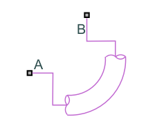
The Pipe Bend (G) block represents a curved pipe in a gas network. You can define the pipe characteristics to calculate losses due to friction and pipe curvature. The block models losses with hydraulic loss coefficients and the results may be more accurate for lower speed flows where you can neglect compressible flow effects.
Pipe Curvature Loss Coefficient
The coefficient for pressure losses due to geometry changes comprises an angle correction factor, Cangle, and a bend coefficient, Cbend:
The block calculates Cangle as:
where θ is the value of the Bend angle parameter, in degrees.
The block calculates Cbend from the tabulated ratio of the bend radius, r, to the pipe diameter, d, for 90° bends from data based on Crane [1]:
| r/d | 1 | 1.5 | 2 | 3 | 4 | 6 | 8 | 10 | 12 | 14 | 16 | 20 | 24 |
|---|---|---|---|---|---|---|---|---|---|---|---|---|---|
| K | 20 fT | 14 fT | 12 fT | 12 fT | 14 fT | 17 fT | 24 fT | 30 fT | 34 fT | 38 fT | 42 fT | 50 fT | 58 fT |
The block interpolates the friction factor, fT, for clean commercial steel from tabular data based on the pipe diameter [1]. This table contains the pipe friction data for clean commercial steel pipe with flow in the zone of complete turbulence.
| Nominal size (mm) | 5 | 10 | 15 | 20 | 25 | 32 | 40 | 50 | 72.5 | 100 | 125 | 150 | 225 | 350 | 609.5 |
|---|---|---|---|---|---|---|---|---|---|---|---|---|---|---|---|
| Friction factor, fT | .035 | .029 | .027 | .025 | .023 | .022 | .021 | .019 | .018 | .017 | .016 | .015 | .014 | .013 | .012 |
The correction factor is valid for a ratio of bend radius to diameter between 1 and 24. Beyond this range, the block employs nearest-neighbor extrapolation.
Losses Due to Friction in Laminar Flows
The pressure loss formulations are the same for the flow at ports A and B.
When the flow in the pipe is fully laminar, or below Re = 2000, the pressure loss over the bend is
where:
μ is the relative humidity.
λ is the Darcy friction factor constant, which is 64 for laminar flow.
ρI is the internal fluid density.
d is the pipe diameter.
L is the bend length segment, which is the product of the Bend radius and the Bend angle parameters:
A is the pipe cross-sectional area,
is the mass flow rate at the respective port.
Losses due to Friction in Turbulent Flows
When the flow is fully turbulent, or greater than Re = 4000, the pressure loss in the pipe is:
where fD is the Darcy friction factor. The block approximates this value by using the empirical Haaland equation and the Internal surface absolute roughness parameter. The block takes the differential over each half of the pipe segment, between port A to an internal node, and between the internal node and port B.
Pressure Differential
The block calculates the pressure loss over the bend based on the internal fluid volume pressure, pI :
Mass Balance
Mass conservation relates the mass flow rates to the dynamics of the pressure and temperature of the internal node representing the gas volume. When you select Enable dynamic compressibility, the mass balance is
where:
is the partial derivative of the mass of the gas volume with respect to pressure at constant temperature and volume.
is the partial derivative of the mass of the gas volume with respect to temperature at constant pressure and volume.
pI is the pressure of the gas volume.
TI is the temperature of the gas volume.
t is time.
A and B are the mass flow rates at ports A and B, respectively. The flow rate at a port is positive when gas flows into the block through that port.
When you clear the Enable dynamic compressibility checkbox, the mass flow into the pipe equals the mass flow out of the pipe
Energy Balance
Energy conservation relates the energy and heat flow rates to the dynamics of the pressure and temperature of the internal node that represents the gas volume. When you select Enable dynamic compressibility, the energy balance is
where:
is the partial derivative of the internal energy of the gas volume with respect to pressure at constant temperature and volume.
is the partial derivative of the internal energy of the gas volume with respect to temperature at constant pressure and volume.
ΦA and ΦB are the energy flow rates at ports A and B, respectively.
When you clear the Enable dynamic compressibility check box, the energy balance is
where:
cp is the gas specific heat.
V is the pipe volume.
ρ0 is the gas density. The block calculates this constant value from the Nominal liquid temperature and Nominal liquid pressure parameters.
Ports
Conserving
Parameters
References
[1] Crane Co. Flow of Fluids Through Valves, Fittings, and Pipe TP-410. Crane Co., 1981.