Aircraft Electric Environmental Control System (eECS)
R2026bThis example models an electric Environmental Control System (eECS) for a commercial passenger aircraft. Unlike traditional pneumatic systems that bleed hot air from the engines, this architecture uses electrically driven turbochargers to compress fresh ram air, improving engine efficiency and reducing fuel consumption. The model simulates a complete air conditioning pack including an electric turbocharger (ETC), a fuel-cooled heat exchanger, an air cycle machine (ACM), a thermal management system with primary and secondary heat exchangers, and cabin thermodynamics with passenger thermal and moisture loads. A hybrid control strategy combines open-loop feedforward commands based on the stages of the flight cycle with closed-loop PI regulation of cabin pressure, temperature, and air flow. The simulation covers a full flight cycle from ground taxi through climb, cruise, descent, and landing.
Model
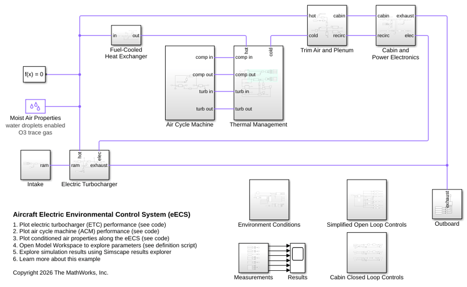
The model consists of the following subsystems connected in an aircraft conditioning pack architecture. Ram air enters the Intake subsystem, where an ozone catalytic converter removes harmful O3 before the air reaches the Electric Turbocharger (ETC) subsystem. The ETC compressor raises the air pressure and temperature. The hot compressed air then splits: the main stream flows through the Fuel-Cooled Heat Exchanger subsystem for initial precooling, while a small fraction bypasses directly to the Trim Air and Plenum subsystem for temperature regulation. The precooled air enters the Thermal Management subsystem and the Air Cycle Machine (ACM) subsystem, where it flows through a primary heat exchanger cooled by external ram air, the ACM compressor, a secondary heat exchanger also cooled by external ram air, a reheater, and a condenser for moisture removal. The ACM turbine then expands the air to achieve low temperatures suitable for cabin cooling. The cold, dry conditioned air exits the Thermal Management subsystem and enters the Trim Air and Plenum subsystem, where it mixes with the hot bypass trim air and recirculated cabin air to achieve the target supply temperature. The mixed air flows to the Cabin and Power Electronics subsystem, which models the pressurized fuselage volume, passenger thermal and moisture loads, and electrical waste heat. Finally, the exhaust air passes through the ETC turbine for power recovery and exits the aircraft through the Outboard subsystem.
There are typically two conditioning packs in an aircraft. This example models only one of the two packs and duplicates the output of the pack to the cabin.
The Environment Conditions subsystem provides atmospheric boundary conditions for the model, while the Simplified Open Loop Controls and Cabin Closed Loop Controls subsystems implement the hybrid control strategy that manages the system across all flight stages.
Intake Subsystem
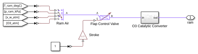
The Intake subsystem models the ram air inlet of the aircraft. It captures ambient air that is pressurized by the aircraft's forward velocity through dynamic pressure recovery. The subsystem includes an ozone catalytic converter that removes atmospheric ozone from the ingested air before it enters the air conditioning pack.
O3 Catalytic Converter Subsystem
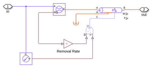
The O3 Catalytic Converter subsystem models the catalytic removal of ozone (O3) from the intake air. At cruise altitudes, atmospheric ozone concentrations can be harmful to passengers. This converter decomposes ozone into diatomic oxygen with a removal efficiency of 80%, ensuring that conditioned cabin air meets air quality standards.
Electric Turbocharger Subsystem
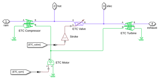
The Electric Turbocharger (ETC) subsystem models an electrically driven compressor-turbine unit. The compressor raises the pressure of the intake air to provide sufficient flow through the downstream heat exchangers and air cycle machine. The turbine extracts energy from the cabin exhaust air, reducing the electrical power required to drive the compressor. An electric motor on the common shaft provides the additional torque needed to maintain the desired compressor speed across all flight conditions.
Fuel-Cooled Heat Exchanger Subsystem
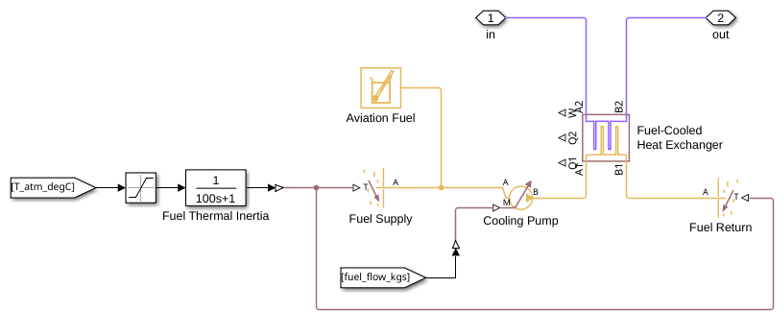
The Fuel-Cooled Heat Exchanger subsystem provides initial cooling of the hot compressed air exiting the ETC compressor. It transfers heat from the conditioned air stream to the aircraft fuel, which serves as a convenient heat sink. This precooling stage reduces the thermal load on the downstream ram-air-cooled heat exchangers in the Thermal Management subsystem.
Thermal Management Subsystem
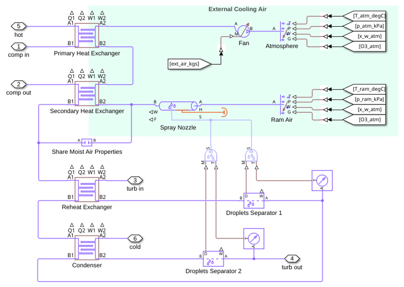
The Thermal Management subsystem contains the core thermodynamic conditioning loop. It includes the Primary Heat Exchanger (PHX) and Secondary Heat Exchanger (SHX), which reject heat to external ram air. A Reheat Exchanger and Condenser form the vapor cycle that removes moisture from the conditioned air. A droplet separator removes any entrained water droplets due to condensation to prevent damage to the ACM turbine. A second droplet separator removes additional droplets that may form during the expansion in the ACM turbine. A fan drives the air flow through the external side of the heat exchangers.
Air Cycle Machine Subsystem
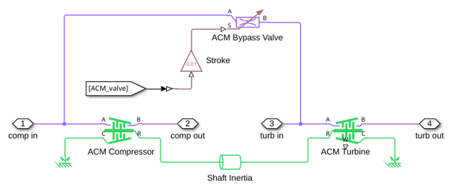
The Air Cycle Machine (ACM) subsystem models a bootstrap air cycle refrigeration unit. A compressor and turbine are mounted on a common shaft with no external power input. After the primary heat exchanger cools down the hot compressed air from the ETC, the ACM compressor further raises the air pressure. The resulting increased temperature allows more heat to be rejected in the secondary heat exchanger. The subsequent ACM turbine then expands the air to achieve colder temperatures than a simple expansion from the original hot compressed air would. The turbine expansion also condenses most remaining moisture into droplets for dehumidification. The balance of compressor and turbine aerodynamic torques determines the ACM shaft speed.
Trim Air and Plenum Subsystem
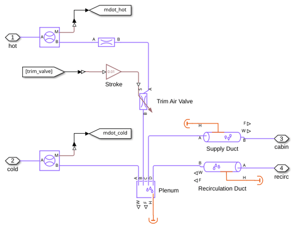
The Trim Air and Plenum subsystem controls the temperature of air delivered to the cabin. A trim air valve bypasses a fraction of the hot air from upstream of the heat exchangers and mixes it with the cold conditioned air and recirculated cabin air in a plenum chamber. The closed-loop temperature controller modulates the valve position to maintain the cabin at the desired setpoint.
Cabin and Power Electronics Subsystem
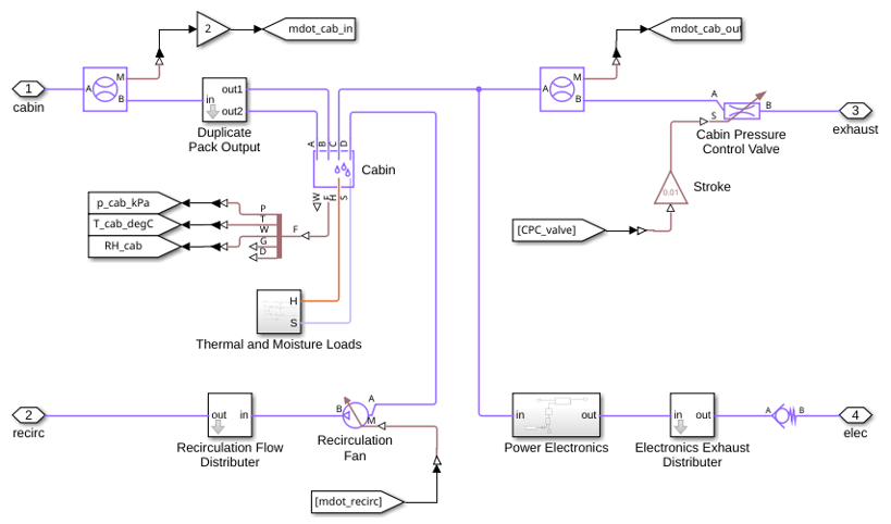
The Cabin and Power Electronics subsystem models the pressurized aircraft fuselage and the avionics equipment bay. The subsystem receives conditioned air from the plenum and recirculates a portion of the air through a recirculation fan to maintain adequate air flow rate for passenger comfort. The power electronics bay generates waste heat that must be removed by the environmental control system. The Duplicate Pack Output subsystem doubles the flow of conditioned air while the Recirculation Flow Distributer and the Electronics Exhaust Distributer halves the flow of returned air to account for the second conditioning pack.
Exhaust air exits through the cabin pressure control valve (CPCV) to maintain the desired cabin pressure, which corresponds to a cabin altitude of approximately 1829 m (6000 ft). The closed-loop cabin pressure controller modulates the valve position.
Thermal and Moisture Loads Subsystem
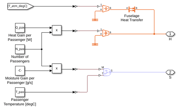
The Thermal and Moisture Loads subsystem calculates the internal heat and moisture generation within the cabin. It models the metabolic contributions of 150 passengers, each producing 70 W of sensible heat and 0.015 g/s of moisture at an exhalation temperature of 30 degC. It also models the heat exchange between the cabin volume and the external atmosphere through the fuselage skin. These loads represent the dominant internal disturbances that the environmental control system must counteract to maintain comfortable cabin conditions.
Power Electronics Subsystem
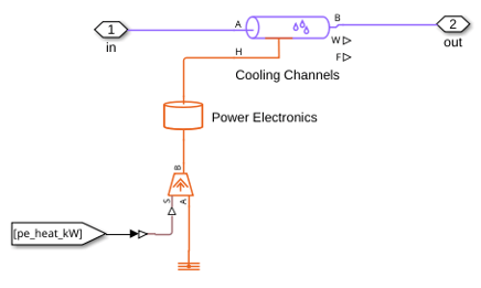
The Power Electronics subsystem models the avionics and electrical equipment bay as a heat source. The waste heat generation varies with flight stage, ranging from 1.5 kW during descent to 5.5 kW during climb. This heat is rejected into the air stream passing through the electronics bay, adding to the overall thermal load on the environmental control system.
Outboard Subsystem
The Outboard subsystem models the exhaust path where conditioned air exits the aircraft.
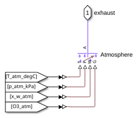
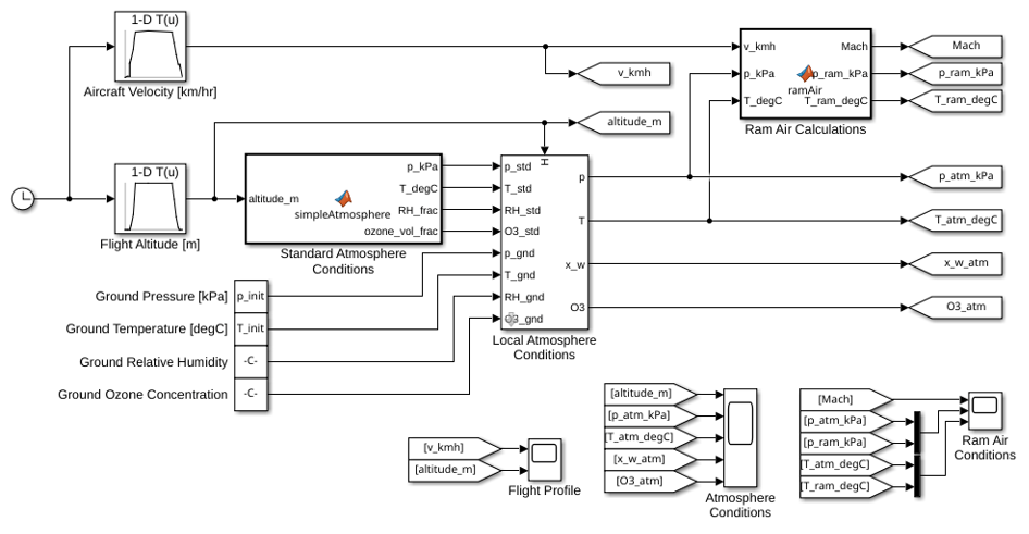
Environment Conditions Subsystem
The Environment Conditions subsystem computes the ambient atmospheric properties as a function of flight altitude and velocity. A Standard Atmosphere block implements the International Standard Atmosphere (ISA) model for pressure and temperature. It also approximates ambient humidity and ozone concentration as a function of altitude. A Local Atmosphere block blends ground-level initial conditions with the ISA model during the initial climb using a linear transition up to 2000 m. A Ram Air Calculations block computes the total pressure and temperature at the intake using isentropic flow relations and the aircraft Mach number.
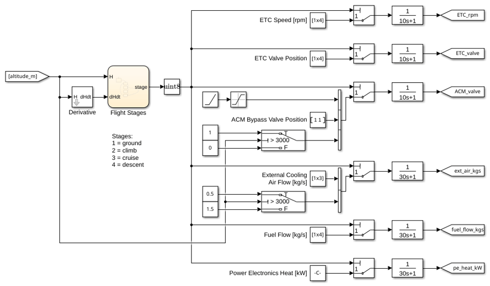
Simplified Open Loop Controls Subsystem
The Simplified Open Loop Controls subsystem provides feedforward setpoints for the ETC motor speed, valve positions, and fan speeds based on the current flight stage. A Stateflow chart detects the flight phase, and first-order filters smooth the command signals to prevent step changes that could cause solver stiffness in the physical model. This open-loop layer ensures stable, predictable system behavior for this example, but a more detailed model would likely require more closed-loop controllers.
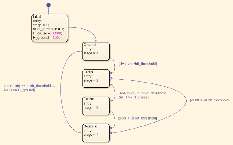
Flight Stages StateFlow Chart
The Flight Stages Stateflow chart implements a state machine that detects the current flight phase based on altitude and rate of altitude change. It transitions among ground, climb, cruise, and descent states. The detected flight stage determines the open-loop setpoints used by the feedforward control layer.
Cabin Closed Loop Controls Subsystem
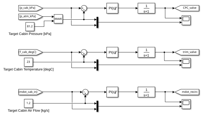
The Cabin Closed Loop Controls subsystem implements PI feedback controllers that regulate cabin conditions. A pressure controller modulates the cabin pressure control valve to maintain the scheduled cabin pressure. A temperature controller adjusts the trim air valve to regulate cabin temperature to the setpoint of 23 degC. A flow rate controller adjusts the recirculation fan to achieve a cabin air flow rate of 1.2 kg/s.
Simulation Results from Scopes
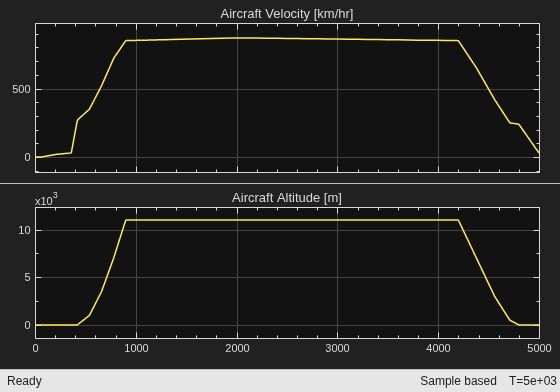
The Flight Profile scope shows the flight mission used in the simulation. The altitude profile covers a full flight cycle from ground level (taxi) to a cruise altitude of 11,000 m, followed by descent and landing. The velocity profile shows the aircraft speed ranging from taxi speeds on the ground up to approximately 870 km/hr at cruise. These profiles define the boundary conditions for the environmental control system.
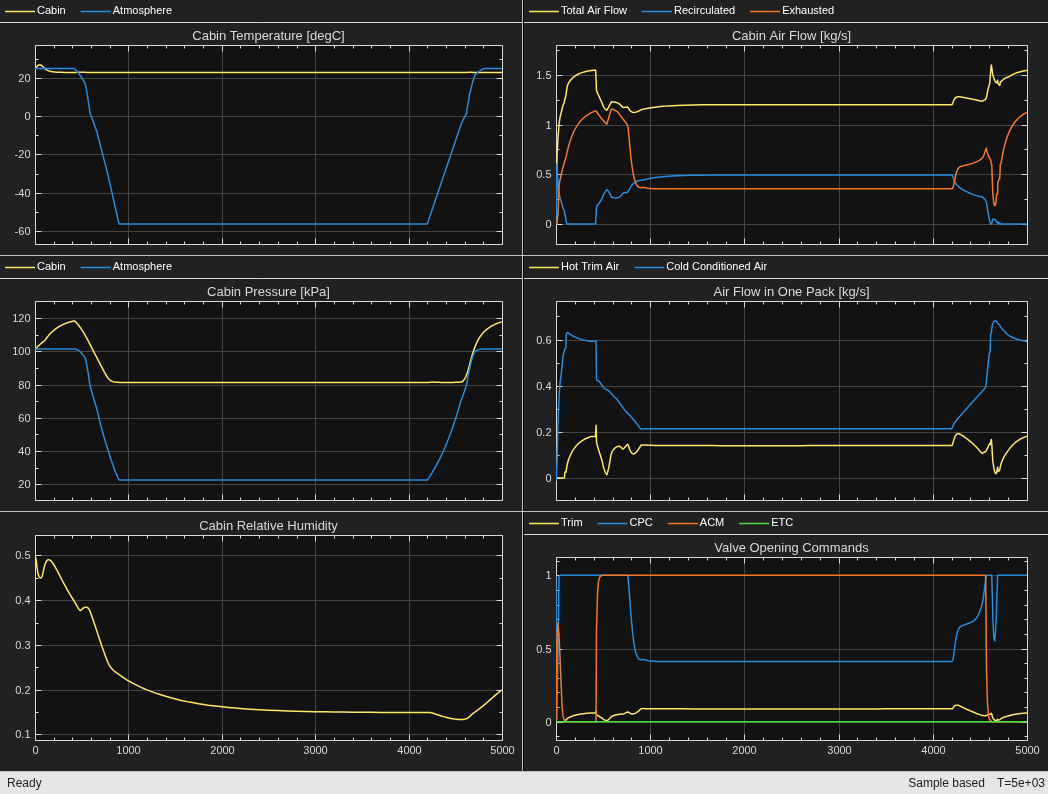
The Results scope shows the cabin environment variables over the flight cycle. Cabin temperature is regulated near the 23 degC setpoint. Cabin pressure is maintained at approximately 81.2 kPa (equivalent to 6,000 ft cabin altitude) during cruise. The system maintains cabin humidity during ground operations but decreases during cruise due to the lack of atmospheric moisture at high altitudes.
Simulation Results from Simscape Logging
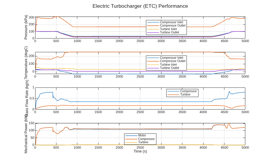
The Electric Turbocharger (ETC) performance plot shows the pressure, temperature, mass flow rate, and mechanical power at the compressor and turbine across the flight cycle. During climb and cruise, the compressor inlet pressure and temperature drop as ambient pressure and temperature decrease with altitude. However, the compressor maintains sufficient outlet pressure and temperature to heat the cabin during cruise. The turbine recovers energy from the exhaust air, reducing the net power needed by the motor to drive the ETC. However, in this model setup, the energy recovery is minimal.
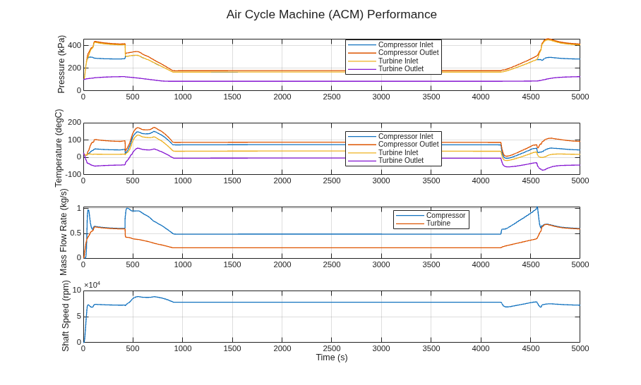
The Air Cycle Machine (ACM) performance plot shows the pressure, temperature, mass flow rate, and shaft speed across the flight cycle. The ACM shaft speed is self-regulating, determined by the torque balance between the compressor and turbine. The compressor and turbine produce the necessary pressure and temperature differences to run the cooling cycle during the ground stage and parts of the climb and descent stages. During cruise, the ACM bypass valve opens to reduce the amount of cooling from the ACM.
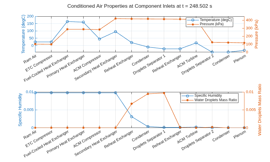
The conditioned air properties plot shows the temperature, pressure, specific humidity, and water droplet content at each component inlet along the air conditioning pack during a representative ground-taxi moment, when cooling demand peaks. This visualization traces the thermodynamic state of the air as it progresses from ram air intake through compression, cooling, moisture removal, and final delivery to the cabin plenum.