VCO Testbench
Validate voltage controlled oscillator (VCO) by measuring phase noise metrics or VCO characteristics

Libraries:
Mixed-Signal Blockset /
PLL /
Measurements & Testbenches
Description
The VCO Testbench block validates the VCO device under test (DUT) by measuring one of the two target metrics: phase noise, or voltage sensitivity and quiescent frequency. You can use the testbench to validate a VCO of your own implementation, or you can use the VCO block from the Mixed-Signal Blockset™.
The VCO Testbench block generates the stimulus (control voltage) to drive the device under test (DUT) from the Stimulus tab. The setup parameters for validating the DUT are defined in the Setup tab and the target validation metrics are defined in the Target Metric tab.
To take the full advantage of the VCO testbench capabilities by using autofill parameters options, use only two blocks, the VCO DUT and the VCO Testbench in the Simulink® model.
Examples
This example shows how to validate the phase noise profile of a VCO device under test (DUT) using a VCO Testbench.
Open the model ringOscVCOPhaseNoise. The model consists of a Ring Oscillator VCO block and a VCO Testbench.
model = 'ringOscVCOPhaseNoise';
open_system(model)
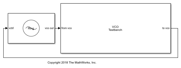
close_system(model)
The voltage sensitivity of the VCO is set to 1.25e6 Hz, and the free running frequency is 2e9 Hz. Check that Add phase noise parameter is enabled. Click the Estimate phase noise parameters button, then click Plot fit to see how the phase noise is fitted against the specification. In the attached model, the fit is good.
The testbencch is set to measure the Phase noise metric of the VCO in the Measurement option. The Control voltage provided to the input of VCO is 4 V. So, the VCO operates at 2.5 GHz frequency. Click the Autofill setup parameters button to automatically calculate the Resolution bandwidth (Hz), and No. of spectral averages. Click the Autofill target metric button to automatically import the phase noise target profile to the VCO Testbench.
Run simulation for 8e-4 s, as recommended in the Block Parameters dialog box.
sim(model);
open_system([model '/VCO Testbench'])
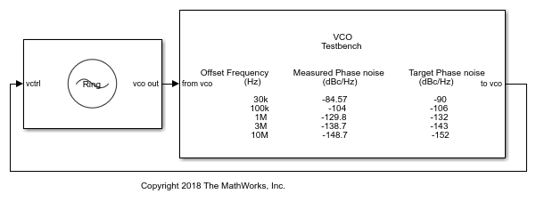
Double click the VCO Testbench block to open the Block Parameters dialog box. Click on the Plot measurement button.

The operating frequency matches the predicted frequency 2.5 GHz. The measured phase noise profile also matches the target profile.
Ports
Input
Output
Parameters
More About
References
[1] Banerjee, Dean. PLL Performance, Simulation and Design. Indianapolis, IN: Dog Ear Publishing, 2006.
Version History
Introduced in R2019a