What Is Camera-IMU Calibration?
R2026bCamera-IMU calibration estimates the SE(3) transformation that defines the spatial relationship between a camera and an IMU in a multi-sensor system.
Camera and Inertial Measurement Unit (IMU) sensors work together in autonomous navigation systems on Unmanned Aerial Vehicles (UAVs) and ground vehicles. The compact size, lower cost, and reduced power consumption make this sensor pairing a popular choice for state estimation.
These images show various mounting setups for camera-IMU sensor pairs on UAVs and ground vehicles. These configurations are important in determining the current state of the vehicle, providing detailed information on three-dimensional translation and orientation with respective to the initial state.


Camera and IMU sensor pairs work very well with each other in state estimation or localization. By fusing measurements from both sensors, the camera can mitigate the impact of noise in IMU data, while the IMU can compensate for tracking losses that the camera might experience. To effectively combine camera-IMU measurements in systems such as factor graphs, it is essential to have an accurate transformation between the camera and IMU sensors. This transformation enables the use of measurements from one coordinate frame to another.
Data Collection Recommendations
To achieve accurate calibration between a camera and an IMU sensor, it is important to follow a set of best practices during the data collection process. These practices ensure that the calibration algorithm has sufficient data to estimate the sensor trajectories and align their coordinate frames. Use these tips to collect quality calibration data:
Use an asymmetric checkerboard that contains an even number of squares along one edge and an odd number of squares along the other edge, with two black corner squares along one side and two white corner squares on the opposite side. This helps camera orientation estimation.
Position the camera-IMU setup in front of a visual calibration target, such as a checkerboard. Ensure that the setup moves enough to register non-zero acceleration and angular velocity, which are critical for estimating the IMU's trajectory.
Maintain consistent visibility of the calibration target throughout the data collection to enable precise estimation of the camera trajectory.
Move the setup at a moderate speed during calibration data collection. Extremely slow movements can result in insufficient IMU data, while overly fast movements can cause motion blur in the camera images.
Avoid fast movements to avoid motion blur in camera image data, which can compromise the accuracy of the camera pose trajectory estimation and the extrinsic calibration.
Rotate the setup around each of the axes of the IMU to accurately determine the relative position of the camera with respect to the IMU along those axes.
Translate the setup along each of the axes of the IMU to accurately determine the relative orientation of the camera with respect to the IMU along those axes.
Avoid performing 180-degree flips when using checkerboard or circle grid calibration targets, as such movements can introduce rotational ambiguities.
For comprehensive rotation and translation data, follow a specific movement pattern that covers all axes of the IMU. Assuming the x-axis points forward toward the calibration board and lies parallel to the ground, the y-axis extends to the left on the same plane, and the z-axis rises perpendicular to the ground, conduct the following movements:
Translate the setup three times on each of x-, y-, and z-axes in both the positive and negative directions.
Rotate the setup three times around each of x-, y-, and z-axes in both clockwise and counterclockwise directions.
Incorporate random 3-D translations and rotations to cover a range of motions.
Keep the setup stationary for a couple of seconds at the start and end of data collection to help IMU bias estimation.
This animation shows an example of a data collection routine showing some of these best practices.

Extrinsic Calibration Process
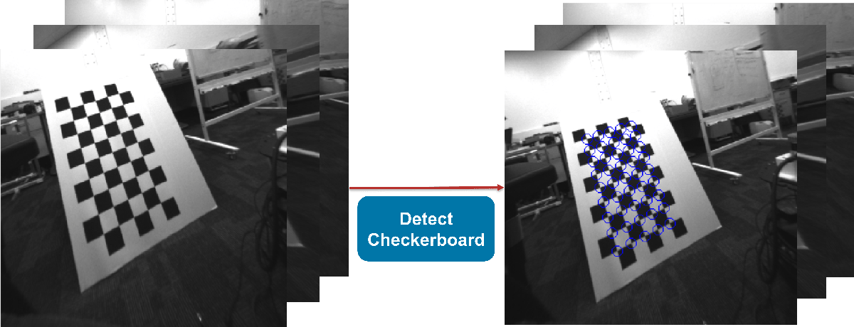
This section illustrates the workflow for the camera and IMU extrinsic calibration process, where you use checkerboard as a visual calibration target.

Detect checkerboard points from the calibration images.
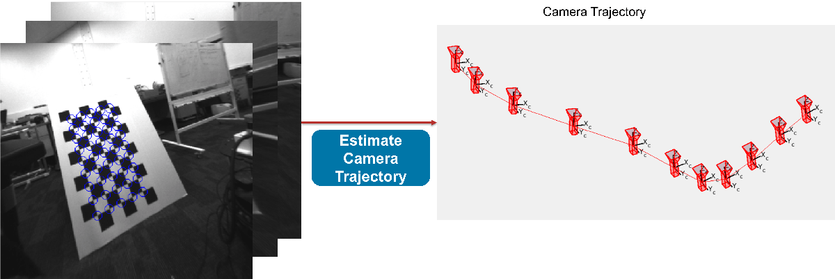
2. Estimate camera trajectory (3-D position + orientation) accurately using detected checkerboard points.
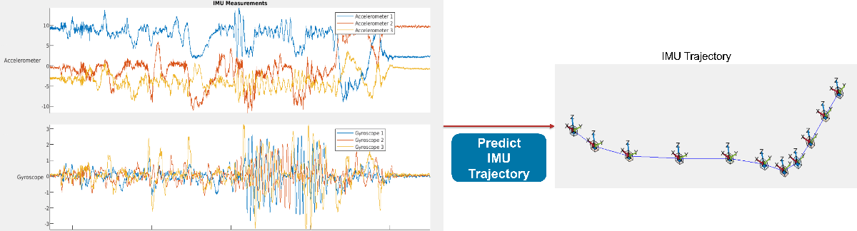
3. Predict IMU trajectory using pre-integration of IMU, Accelerometer and Gyroscope
measurements. You can use the predict function to do this.
4. Align camera and IMU trajectories to estimate 3-D rotation and translation from camera to IMU.

See Also
estimateCameraIMUTransform | factorGraph
Topics
- Monocular Visual-Inertial Odometry (VIO) Using Factor Graph
- Performant and Deployable Monocular Visual SLAM
- What Is Multi-Sensor Calibration? (Computer Vision Toolbox)
- What Is Multi-Camera Calibration? (Computer Vision Toolbox)
- What Is Lidar-Camera Calibration? (Point Cloud Toolbox)

