Pillow Block Bearing Geometry
Create a geometry of a pillow block bearing by using the MATLAB® functions polyshape and polybuffer, and the geometry modification functions available in Partial Differential Equation™ Toolbox.
First, create a polygonal shape representing a profile of the pillow block bearing in the x-z plane by using the polyshape function.
shapexz = polyshape( ...
    [-50,50,50,10,10,-10,-10,-50],...
    [-10,-10,20,20,70,70,20,20]);
plot(shapexz)

To smooth the corners of the shape: buffer the original shape by a small distance, shrink the shape by twice that distance, and then buffer the resulting shape by the same distance again. This process produces a polyshape object that approximately matches the original shape, but has smooth inside and outside corners.
First, create a buffer at a distance of 6 from the boundaries by using the polybuffer function.
shapexz = polybuffer(shapexz,6);
plot(shapexz)

To round the inside corners, shrink the new boundaries by a distance of 12.
shapexz = polybuffer(shapexz,-12);
plot(shapexz)

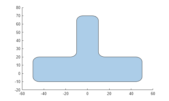
To round the outside corners, create another buffer by a distance of 6 from the new boundaries.
shapexz = polybuffer(shapexz,6);
plot(shapexz)
Next, cut a piece from the bottom of the shape. Start by creating another polygonal shape named chop representing the piece to cut from the bottom.
chop = polyshape([-60,-38,-38,38,38,60,60,-60],...
                 [0,0,8,8,0,0,-20,-20]);
plot([shapexz,chop])
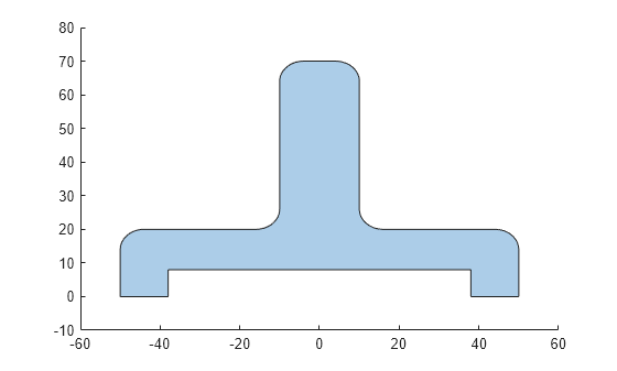
To cut one polygonal shape from another, use the subtract function.
shapexz = subtract(shapexz,chop);
plot(shapexz)
Convert the polyshape object into a triangulation object.
g1 = triangulation(shapexz);
Create an fegeometry object from the triangulation object.
g1 = fegeometry(g1);
Extrude the resulting 2-D geometry into 3-D.
g1 = extrude(g1,40);
pdegplot(g1)
Rotate the geometry by 90 degrees around the x-axis.
g1 = rotate(g1,90,[0,0,0],[1,0,0]);
pdegplot(g1)
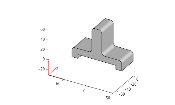
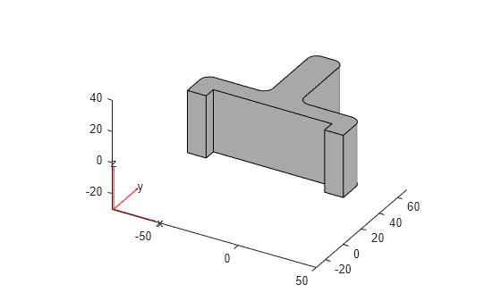
Move the geometry along the y-axis.
g1 = translate(g1,[0,20,0]);
pdegplot(g1)

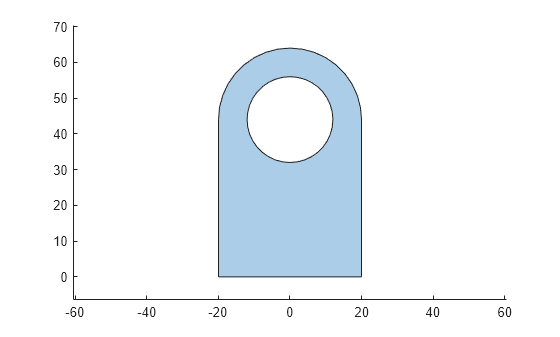
Create a polygonal shape representing the profile of the pillow block bearing in the y-z plane by using the polyshape function.
shapeyz = polyshape([-20,20,20*cosd(0:10:180), ...
                   -20,NaN,12*cosd(0:10:360)],...
                   [0,0,44+20*sind(0:10:180),0, ...
                   NaN,44+12*sind(0:10:360)]);
plot(shapeyz)
axis equal
Convert the polyshape object into a triangulation object.
g2 = triangulation(shapeyz);
Create an fegeometry object from the triangulation object.
g2 = fegeometry(g2);
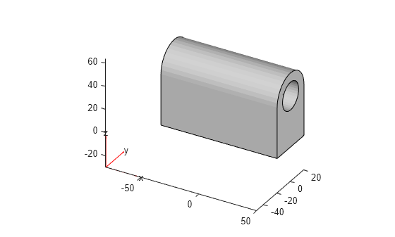
Extrude the resulting 2-D geometry into 3-D.
g2 = extrude(g2,100);
pdegplot(g2)

Rotate the geometry by 90 degrees around the x-axis, and then rotate the resulting geometry by 90 degrees around the z-axis.
g2 = rotate(g2,90,[0,0,0],[1,0,0]);
g2 = rotate(g2,90,[0,0,0],[0,0,1]);
pdegplot(g2)

Move the geometry along the x-axis.
g2 = translate(g2,[-50,0,0]);
pdegplot(g2)
Intersect the geometries.
result = intersect(g1,g2);
Display the intersection by plotting g1 in green, g2 in red, and the resulting geometry in blue. Set the surface transparency for g1 and g2 to 0.2 by using FaceAlpha.
figure
pdegplot(result,FaceColor="blue");
hold on
pdegplot(g1,FaceAlpha=0.2,FaceColor="green")
hold on
pdegplot(g2,FaceAlpha=0.2,FaceColor="red")

Create the cylinder geometry that you can use to make holes on both sides of the pillow block bearing.
hole = fegeometry(multicylinder(6,40));
pdegplot(hole)

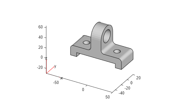
Subtract a cylinder geometry to make two holes. The resulting geometry represents the pillow block bearing.
result = subtract(result,translate(hole,[-30,0,0]));
result = subtract(result,translate(hole,[30,0,0]));
figure
pdegplot(result)