phased.OmnidirectionalMicrophoneElement
Omnidirectional microphone element
Description
The phased.OmnidirectionalMicrophoneElement
System object™ models a microphone element with an omnidirectional response pattern.
To compute the response of the microphone element for specified directions:
Create the
phased.OmnidirectionalMicrophoneElementobject and set its properties.Call the object with arguments, as if it were a function.
To learn more about how System objects work, see What Are System Objects?
Creation
Syntax
Description
microphone = phased.OmnidirectionalMicrophoneElementmicrophone, with default object properties.
microphone = phased.OmnidirectionalMicrophoneElement(Name=Value)microphone, with each
specified property set to the specified value. You can specify additional name-value pair
arguments in any order as
(Name1=Value1,...,NameN=ValueN).
Example: microphone =
phased.OmnidirectionalMicrophoneElement(FrequencyRange=[0
1000],BackBaffled=true) creates a back baffled omnidirectional microphone
element with its frequency range specified between 0 and 1000 Hz.
Properties
Usage
Description
RESP = microphone(FREQ,ANG)RESP, at frequencies
specified in FREQ and directions specified in
ANG.
Note
The object performs an initialization the first time the object is executed. This
initialization locks nontunable properties
and input specifications, such as dimensions, complexity, and data type of the input data.
If you change a nontunable property or an input specification, the System object issues an error. To change nontunable properties or inputs, you must first
call the release method to unlock the object.
Input Arguments
Output Arguments
Object Functions
To use an object function, specify the
System object as the first input argument. For
example, to release system resources of a System object named obj, use
this syntax:
release(obj)
Examples
Create an omnidirectional microphone. Find the microphone response at 200, 300, and 400 Hz for the incident angle 0° azimuth and 0° elevation. Then, plot the azimuth response of the microphone at three frequencies.
microphone = phased.OmnidirectionalMicrophoneElement;
microphone.FrequencyRange=[20 2e3];
fc = [200 300 400];
ang = [0;0];
resp = microphone(fc,ang);
Plot the response pattern. The response patterns for at all three frequencies are the same.
pattern(microphone,fc,-180:180,0,'CoordinateSystem','polar','Type','power');

Compute the directivity of an omnidirectional microphone element for several different directions.
Create the omnidirectional microphone element system object.
myMic = phased.OmnidirectionalMicrophoneElement();
Select the angles of interest at constant elevation angle set equal to zero degrees. Select seven azimuth angles centered at boresight (zero degrees azimuth and zero degrees elevation). Finally, set the desired frequency to 1 kHz.
ang = [-30,-20,-10,0,10,20,30; 0,0,0,0,0,0,0];
freq = 1000;
Compute the directivity along the constant elevation cut.
d = directivity(myMic,freq,ang)
d = 7×1

     0
     0
     0
     0
     0
     0
     0
Next select the angles of interest to be at constant azimuth angle at zero degrees. All elevation angles are centered around boresight. The five elevation angles range from -20 to +20 degrees. Set the desired frequency to 1 GHz.
ang = [0,0,0,0,0; -20,-10,0,10,20];
freq = 1000;
Compute the directivity along the constant azimuth cut.
d = directivity(myMic,freq,ang)
d = 5×1

     0
     0
     0
     0
     0
For an omnidirectional microphone, the directivity is independent of direction.
Determine whether a phased.OmnidirectionalMicrophoneElement microphone element supports polarization.
microphone = phased.OmnidirectionalMicrophoneElement;
isPolarizationCapable(microphone)
ans = logical
   0
The returned value 0 shows that the omnidirectional microphone element does not support polarization.
Construct an omnidirectional microphone and plot the magnitude and directivity patterns. The microphone operating frequency spans the range 20 to 20000 Hz.
Construct the omnidirectional microphone.
sOmni = phased.OmnidirectionalMicrophoneElement(...
    'FrequencyRange',[20 20e3]);
Plot the microphone magnitude pattern at 200 Hz.
fc = 200;
pattern(sOmni,fc,[-180:180],0,...
    'CoordinateSystem','rectangular',...
    'Type','efield')

Plot the microphone directivity.
pattern(sOmni,fc,[-180:180],0,...
    'CoordinateSystem','rectangular',...
    'Type','directivity')

The directivity is 0 dbi as expected for an omnidirectional element.
Construct an omnidirectional microphone with response in the frequency range 20-20000 Hz. Then, plot the 3-D magnitude pattern over a range of angles.
Construct the microphone element.
sOmin = phased.OmnidirectionalMicrophoneElement(...
    'FrequencyRange',[20 20e3]);
Plot the 3-D pattern at 500 Hz between -30 to 30 degrees in both azimuth and elevation in 0.1 degree increments.
fc = 500;
pattern(sOmin,fc,[-30:0.1:30],[-30:0.1:30],...
    'CoordinateSystem','polar',...
    'Type','efield')

Create an omnidirectional microphone element. Plot an azimuth cut of the directivity at 0 and 30 degrees elevation. Assume an operating frequency of 500 Hz.
Create the microphone element.
sOmni = phased.OmnidirectionalMicrophoneElement('FrequencyRange',[100,900]);
fc = 500;
Plot the azimuth pattern.
patternAzimuth(sOmni,fc,[0 30])
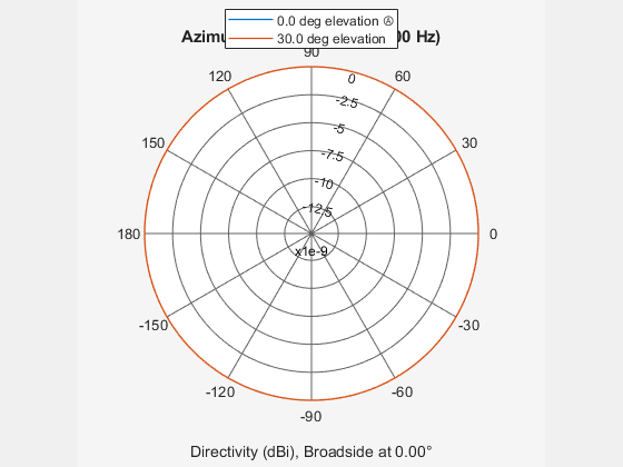
Because of the omnidirectionality of the microphone, the two patterns coincide.
Plot a reduced range of azimuth angles using the Azimuth parameter.
patternAzimuth(sOmni,fc,[0 30],'Azimuth',[-20:20])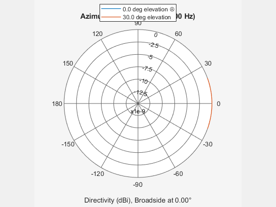
Construct an omnidirectional microphone element. Plot an elevation cut of the power 45 and 55 degrees azimuth. Assume the operating frequency is 500 Hz.
Create the microphone element.
fc = 500;
sOmni = phased.OmnidirectionalMicrophoneElement('FrequencyRange',[100,900]);
Display the power pattern.
patternElevation(sOmni,fc,[45 55],'Type','powerdb')

Because of the omnidirectionality, the two plots coincide.
Plot a reduced range of elevation angles using the Elevation parameter.
patternElevation(sOmni,fc,[45 55],...
    'Elevation',[-20:20],...
    'Type','powerdb')

Extended Capabilities
Version History
Introduced in R2011a