Massive MIMO Hybrid Beamforming
This example shows how to use hybrid beamforming at the transmit end of a massive MIMO communications system, using multi-user and single-user systems techniques. The example determines the channel state information at the transmitter by using full channel sounding. It partitions the required precoding into digital baseband and analog RF components, using different techniques for multi-user and single-user systems. The example computes EVM and BER communications system figures of merit to compare the signal recovered by simplified all-digital receivers to the multiple transmitted data streams.
In the example a scattering-based spatial channel technique models the transmit/receive spatial locations and antenna patterns. A simpler static-flat MIMO channel is also offered for link validation purposes.
Introduction
The ever-growing demand for high data rate and more user capacity increases the need to use the available spectrum more efficiently. Multi-user MIMO (MU-MIMO) improves the spectrum efficiency by allowing a base station (BS) transmitter to communicate simultaneously with multiple mobile stations (MS) receivers using the same time-frequency resources. Massive MIMO allows the number of BS antenna elements to be on the order of tens or hundreds, thereby also increasing the number of data streams in a cell to a large value.
5G wireless systems use millimeter wave (mmWave) bands to take advantage of their wider bandwidth. The 5G systems also deploy large scale antenna arrays to mitigate severe propagation loss in the mmWave band.
The small mmWave band wavelengths allow an array to contain more elements within the same physical dimension. It becomes much more expensive to provide one transmit-receive (TR) module, or an RF chain, for each antenna element. Hybrid transceivers are a practical solution as they use a combination of analog beamformers in the RF and digital beamformers in the baseband domains, with fewer RF chains than the number of transmit elements [ 1 ].
Hybrid Beamforming
Hybrid beamforming (also known as hybrid precoding) is a method that enables the use of massive MIMO antenna arrays in a lower power and cost-efficient manner [ 1 ]. In a traditional antenna array, each antenna requires a dedicated RF chain to transmit and receive each data stream; with hybrid precoding, each stream requires a dedicated RF chain. This greatly reduces the number of RF chains, thus reducing cost and power. The analog outputs of each chain are combined into a network of analog RF gains and phase shifters (the analog RF beamformer, denoted Frf) that are connected to a large antenna array, where the number of antennas >> number of streams. These analog units cannot change weights quickly; however the computed RF weights change slowly over time since they are primarily determined by spatial positions of receivers. The digital baseband precoding weights (denoted Fbb) may change from symbol to symbol due to smaller-scale multipath effects, and may also be different from subcarrier to subcarrier to account for frequency-selective fading.

This example uses a single-user or multi-user MIMO-OFDM system to highlight the partitioning of the required precoding into its digital baseband and RF analog components at the transmitter end. The example uses the orthogonal matching pursuit (OMP) algorithm [ 3 ] for a single-user system and the joint spatial division multiplexing (JSDM) technique [ 2, 4 ] for a multi-user system, to determine the digital baseband Fbb and RF analog Frf precoding weights for the selected system configuration. Building on the system highlighted in the MIMO-OFDM Precoding with Phased Arrays example, this example shows the formulation of the transmit-end precoding matrices and their application to a MIMO-OFDM system.
Virtual Sectorization Using Joint Spatial Division Multiplexing
JSDM takes advantage of spatial clustering of users within the cell and groups these clusters to create virtual sectors via RF analog beamforming to these groups. The spatial covariance matrices of the groups are related to the spatial direction of the groups with respect to the base station antenna array. These matrices are computed using the channel estimates produced from the sounding signals, and the analog RF beams are derived from these matrices. These beams focus transmitted energy to the respective groups and minimize intergroup interference.

Once the beams are formed, the digital precoding weights are computed and used to orthogonalize users within each of the groups. These precoding weights are based on the user's channel state information (CSI) of the "effective channel" as seen from the output of the RF chains (not the output of the antenna array). Such beam-based measurements are done in 5G systems.
Because the analog RF gains and phase shifters are done at the antennas, it is implied that the RF weights apply across all subcarriers. However, the digital precoding weights may be applied per subcarrier. In this example, each subcarrier applies digital precoding weights as computed from the subcarrier's CSI.
s = rng(67); % Set RNG state for repeatability
System Parameters
Define system parameters for the example. Modify these parameters to explore their impact on the system.
prm.fc = 28e9;               % 28 GHz system
prm.chanSRate = 100e6;       % Channel sampling rate, 100 Msps
prm.ChanType = 'Scattering'; % Channel options: 'Scattering', 'MIMO'
prm.NFig = 8;                % Noise figure (increase to worsen, 5-10 dB)
prm.nRays = 500;             % Number of rays for Frf, Fbb partitioning

% Each user has the same modulation
prm.bitsPerSubCarrier = 4;          % 2: QPSK, 4: 16QAM, 6: 64QAM, 8: 256QAM
prm.numDataSymbols = 10;            % Number of OFDM data symbols

% Create a vector of users where each element is a user and the value of
% that element describes the number of independent data streams. For a
% single user case, make this a scalar value.
prm.numSTSVec = [4 3 2 4 3];        % Number of independent data streams per user
prm.numSTS    = sum(prm.numSTSVec); % Must be a power of 2
prm.numTx     = prm.numSTS*8;       % Number of BS transmit antennas (power of 2)
Assign each user to a group. Users are randomly arranged around the center of each group. For a single user use case, the concept of grouping is not applicable, and the user is randomly placed in the cell.
% The group assignments for the active users must be in ascending
% order. The default setting matches the group diagram above; there are two
% groups of users with the first three users assigned to group one and the
% last two users assigned to group two.
prm.groups    = [1 1 1 2 2];  % Describes which users are in which groups
Two JSDM options are available for simulation. This option determines the method for computing the digital precoding weights; the RF analog weights are calculated independent of which option is chosen.
'JGP': Joint Spatial Division Multiplexing with Joint Group Processing (JGP). MIMO streams are precoded based on the CSI feedback of the channel estimates for all users.
'PGP': Joint Spatial Division Multiplexing with Per-Group Processing (PGP). This is a special case where user CSI feedback is reduced to only send back the CSI of the streams transmitted to the user's group, thus increasing available bandwidth that was reserved for CSI feedback. Performance is slightly worse than JGP since precoding is done only on the streams for each group, and is particularly sensitive to the rank of the channel relative to the number of transmitted streams.
prm.jsdmType = 'JGP'; % JSDM option: 'JGP' or 'PGP' (for multi-user simulation)
Note that selecting the MIMO channel via the ChanType parameter field will cause sub-optimal performance for JSDM, since the MIMO channel is not location-aware. If using a scattering channel, add in an additional receiver in each group to improve the channel rank of the group's observed covariance matrix and support the number of streams being transmitted to each group. These receivers are not actively receiving data, but are considered connected to the base station as part of a group.
prm.numSTSVecAll = prm.numSTSVec;       % Number of independent data streams per user
prm.numUsers  = length(prm.numSTSVec);  % Number of active users
prm.numGroups = max(prm.groups);  % Number of groups
numGroups = prm.numGroups;
if strcmp(prm.ChanType,'Scattering')
    for g = 1:numGroups
        prm.groups(prm.numUsers+g) = g;
        prm.numSTSVecAll(prm.numUsers+g) = 2;
    end
end

% Define the center of each group's range, azimuth, and elevation,
% assuming the BS is at the origin.
%   Angles specified as [azimuth;elevation] degrees
% Note: the number of columns must equal the number of groups
maxRange = 700;            % all MSs within 700 meters of BS
groupRanges = randi([1 maxRange],1,numGroups);
groupAzimuth = -60 + 60/(numGroups+1) + ...
    (120-(120/(numGroups+1)))/(numGroups-1) * (0:numGroups-1);
groupElevations = randi([-10 10],1,numGroups);

% Position mobile units
prm.numConnectedUsers = length(prm.numSTSVecAll); % Number of connected users
if prm.numUsers == 1
    % For a single user, randomly place the user
    % MS positions: assumes BS at origin
    %   Angles specified as [azimuth;elevation] degrees
    %   az in range [-180 180], el in range [-90 90], e.g. [45;0]
    prm.mobileRanges = randi([1 maxRange],1,prm.numConnectedUsers);
    prm.mobileAngles = [rand(1,prm.numConnectedUsers)*360-180; ...
                        rand(1,prm.numConnectedUsers)*180-90];
else
    % For multiple users, randomly place the users within their assigned
    % group locations
    prm.mobileRanges = zeros(prm.numConnectedUsers,1);
    prm.mobileAngles = zeros(2,prm.numConnectedUsers);
    for uIdx = 1:prm.numConnectedUsers
        g = prm.groups(uIdx);
        prm.mobileRanges(uIdx)   = groupRanges(g) + 30*rand(1);
        prm.mobileAngles(:,uIdx) = ...
            [groupAzimuth(g)+3*rand(1); groupElevations(g)+3*rand(1)];
    end
end
Define OFDM modulation parameters used for the system.
prm.FFTLength = 256;
prm.CyclicPrefixLength = 64;
prm.numCarriers = 234;
prm.NullCarrierIndices = [1:7 129 256-5:256]'; % Guards and DC
prm.PilotCarrierIndices = [26 54 90 118 140 168 204 232]';
nonDataIdx = [prm.NullCarrierIndices; prm.PilotCarrierIndices];
prm.CarriersLocations = setdiff((1:prm.FFTLength)', sort(nonDataIdx));
prm.numRx = prm.numSTSVecAll;   % Number of receive antennas, per connected user

numSTS = prm.numSTS;
numTx = prm.numTx;
numRx = prm.numRx;
numSTSVec = prm.numSTSVec;
numUsers = prm.numUsers;
codeRate = 1/3;             % same code rate per user
numTails = 6;               % number of termination tail bits
prm.numFrmBits = numSTSVec.*(prm.numDataSymbols*prm.numCarriers* ...
                 prm.bitsPerSubCarrier*codeRate)-numTails;
prm.modMode = 2^prm.bitsPerSubCarrier; % Modulation order
% Account for channel filter delay
numPadSym = 3;          % number of symbols to zero pad
prm.numPadZeros = numPadSym*(prm.FFTLength+prm.CyclicPrefixLength);
Define transmit and receive arrays and positional parameters for the system.
prm.cLight = physconst('LightSpeed');
prm.lambda = prm.cLight/prm.fc;

% Get transmit and receive array information
prm.numSTSVec = prm.numSTSVecAll; % get array info for all connected users
prm.numUsers = prm.numConnectedUsers;
[isTxURA,expFactorTx,isRxURA,expFactorRx] = helperArrayInfo(prm,true);
prm.numSTSVec = numSTSVec;             % restore parameters to active users
prm.numUsers = numUsers;

% Transmit antenna array definition
%   Array locations and angles
prm.posTx = [0;0;0];       % BS/Transmit array position, [x;y;z], meters
if isTxURA
    % Uniform Rectangular array
    txarray = phased.PartitionedArray(...
        'Array',phased.URA([expFactorTx numSTS],0.5*prm.lambda),...
        'SubarraySelection',ones(numSTS,numTx),'SubarraySteering','Custom');
else
    % Uniform Linear array
    txarray = phased.ULA(numTx, 'ElementSpacing',0.5*prm.lambda, ...
        'Element',phased.IsotropicAntennaElement('BackBaffled',false));
end
prm.posTxElem = getElementPosition(txarray)/prm.lambda;

spLoss = zeros(prm.numConnectedUsers,1);
prm.posRx = zeros(3,prm.numConnectedUsers);
for uIdx = 1:prm.numConnectedUsers

    % Receive arrays
    if isRxURA(uIdx)
        % Uniform Rectangular array
        rxarray = phased.PartitionedArray(...
            'Array',phased.URA([expFactorRx(uIdx) numRx(uIdx)], ...
            0.5*prm.lambda),'SubarraySelection',ones(numRx(uIdx), ...
            numRx(uIdx)),'SubarraySteering','Custom');
        prm.posRxElem = getElementPosition(rxarray)/prm.lambda;
    else
        if numRx(uIdx)>1
            % Uniform Linear array
            rxarray = phased.ULA(numRx(uIdx), ...
                'ElementSpacing',0.5*prm.lambda, ...
                'Element',phased.IsotropicAntennaElement);
            prm.posRxElem = getElementPosition(rxarray)/prm.lambda;
        else
            rxarray = phased.IsotropicAntennaElement;
            prm.posRxElem = [0; 0; 0]; % LCS
        end
    end

    % Mobile positions
    [xRx,yRx,zRx] = sph2cart(deg2rad(prm.mobileAngles(1,uIdx)), ...
                             deg2rad(prm.mobileAngles(2,uIdx)), ...
                             prm.mobileRanges(uIdx));
    prm.posRx(:,uIdx) = [xRx;yRx;zRx];
    [toRxRange,toRxAng] = rangeangle(prm.posTx,prm.posRx(:,uIdx));
    spLoss(uIdx) = fspl(toRxRange,prm.lambda);
end
Channel State Information
For a spatially multiplexed system, availability of channel information at the transmitter allows for precoding to be applied to maximize the signal energy in the direction and channel of interest. Under the assumption of a slowly varying channel, this is facilitated by sounding the channel first. The BS sounds the channel by using a reference transmission, that the MS receiver uses to estimate the channel. The MS transmits the channel estimate information back to the BS for calculation of the precoding needed for the subsequent data transmission.
The following schematic shows the processing for the channel sounding modeled.
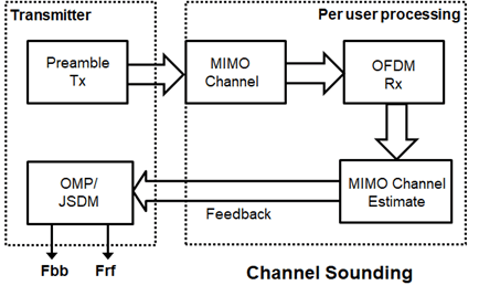
For the chosen MIMO system, a preamble signal is sent over all transmitting antenna elements, and processed at the receiver accounting for the channel. The receiver antenna elements perform pre-amplification, OFDM demodulation, and frequency domain channel estimation for all links.
% Generate the preamble signal
prm.numSTS = numTx;             % set to numTx to sound out all channels
[preambleSig, pilotsym] = helperGenPreamble(prm);
cfg = ofdmPilotConfig(FFTLength = prm.FFTLength, NumGuardBandCarriers = [7;6], NumSymbols = prm.numSTS, ...
                      NumTransmitStreams = prm.numSTS, StreamGroups = {1:prm.numSTS}, ...
                      PilotLocations = {ofdmPilotGrid(1,1:prm.numSTS,prm.CarriersLocations,1)}, ...
                      PilotSymbols = {permute(pilotsym(prm.CarriersLocations,:,:),[2 3 1])});
validate(cfg);

% Transmit preamble over channel
prm.numSTS = numSTS;            % keep same array config for channel
prm.numUsers = prm.numConnectedUsers; % transmit sounding to all connected users
prm.numSTSVec = prm.numSTSVecAll; % transmit sounding to all connected users
[rxPreSig,chanDelay] = helperApplyMUChannel(preambleSig,prm,spLoss);
prm.numUsers = numUsers;
prm.numSTSVec = numSTSVec;

% Channel state information feedback
hDp = cell(prm.numConnectedUsers,1);
prm.numSTS = numTx;             % set to numTx to estimate all links
for uIdx = 1:prm.numConnectedUsers

    % Front-end amplifier gain and thermal noise
    rxPreAmp = phased.ReceiverPreamp( ...
        'Gain',spLoss(uIdx), ...    % account for path loss
        'NoiseFigure',prm.NFig,'ReferenceTemperature',290, ...
        'SampleRate',prm.chanSRate);
    rxPreSigAmp = rxPreAmp(rxPreSig{uIdx});
    %   scale power for used sub-carriers
    rxPreSigAmp = rxPreSigAmp * (sqrt(prm.FFTLength - ...
        length(prm.NullCarrierIndices))/prm.FFTLength);

    % OFDM demodulation
    rxOFDM = ofdmdemod(rxPreSigAmp(chanDelay(uIdx)+1: ...
        end-(prm.numPadZeros-chanDelay(uIdx)),:),prm.FFTLength, ...
        prm.CyclicPrefixLength,prm.CyclicPrefixLength);

    % Channel estimation from preamble
    %       numCarr, numTx, numRx
    hEst = ofdmChannelEstimate(rxOFDM((cfg.NumGuardBandCarriers(1)+1):(cfg.FFTLength - cfg.NumGuardBandCarriers(2)),1:numTx,:),...
                               cfg,prm.CyclicPrefixLength,"Algorithm","leastsquares");
    hDp{uIdx} = squeeze(hEst(prm.CarriersLocations-cfg.NumGuardBandCarriers(1),1,:,:));
end
prm.numSTS = numSTS;                 % revert back for data transmission
prm.numRx  = prm.numRx(1:numUsers);  % set numRx to number of active users
For a single-user system, the OMP partitioning algorithm is sensitive to the array response vectors At. Ideally, these response vectors account for all the scatterers seen by the channel, but these are unknown for an actual system and channel realization, so a random set of rays within a 3-dimensional space to cover as many scatterers as possible is used. The prm.nRays parameter specifies the number of rays.
For a multi-user system, the JSDM algorithm requires the calculation of the spatial covariance from each group to calculate the RF beamformer weights based on the block diagonalization method [ 5 ]. The channel estimate is fed back from each MS, and used by the BS to determine the precoding weights. The example assumes perfect feedback with no quantization or implementation delays. The effective channel is calculated from the RF beamformer weights and the CSI, and the digital baseband precoder weights are then calculated.
% Calculate the hybrid weights on the transmit side
if numUsers==1
    % Single-user OMP
    %   Spread rays in [az;el]=[-180:180;-90:90] 3D space, equal spacing
    %   txang = [-180:360/prm.nRays:180; -90:180/prm.nRays:90];
    txang = [rand(1,prm.nRays)*360-180;rand(1,prm.nRays)*180-90]; % random
    At = steervec(prm.posTxElem,txang);
    AtExp = complex(zeros(prm.numCarriers,size(At,1),size(At,2)));
    for carrIdx = 1:prm.numCarriers
        AtExp(carrIdx,:,:) = At; % same for all sub-carriers
    end

    % Orthogonal matching pursuit hybrid weights
    [Fbb,Frf] = omphybweights(hDp{1},numSTS,numSTS,AtExp);

    v = Fbb;    % set the baseband precoder (Fbb)
    % Frf is same across subcarriers for flat channels
    mFrf = permute(mean(Frf,1),[2 3 1]);

else
    % Multi-user Joint Spatial Division Multiplexing

    % Get number of streams per group
    prm.numSTSGroupVec = zeros(1,numGroups);
    for g = 1:numGroups
        prm.numSTSGroupVec(g) = sum(prm.numSTSVecAll(prm.groups(1:prm.numUsers)==g));
    end

    % Get Rg (group covariances)
    % Note that there is only one R per group (not per user). It is up to the
    % caller to determine how this autocorrelation matrix is obtained from the
    % group.
    hcov = helperGetCovariance(hDp,prm);

    % Calculate the analog beamformer weights
    Bg = jsdmrfweights(hcov,prm.numSTSGroupVec);

    % Pack beamformer weights into a precoding array
    mFrf = cat(1,Bg{:});

    % Calculate (predict) the effective channel response for each user from
    % a beamformed sounding signal
    hEff = helperGetHeff(hDp,mFrf,prm);

    % Get the digital (baseband) weights
    Fbb = jsdmbbweights(hEff,prm.numSTSGroupVec,Bg);

    if strcmp(prm.jsdmType,'PGP')
        % Pack the per group CSI into a matrix (block diagonal) for PGP
        v = zeros(prm.numCarriers,sum(numSTSVec),sum(numSTSVec));
        for g = 1:prm.numGroups
            stsIdx = sum(prm.numSTSGroupVec(1:g-1))+(1:prm.numSTSGroupVec(g));
            v(:,stsIdx,stsIdx) = Fbb{g};  % Nst-by-Nsts-by-Nsts
        end
    else
        % JGP
        v = Fbb;
    end

end
Plot the transmit array pattern. For a scattering channel, the beam directions should correlate closely with the spatial positions of the users, and the beam magnitude should correlate with the number of streams being sent in that direction.
% Transmit array pattern plots
figure;
if isTxURA
    % URA element response for the first subcarrier
    pattern(txarray,prm.fc,-180:180,-90:90,'Type','efield', ...
            'ElementWeights',mFrf.'*squeeze(v(1,:,:)), ...
            'PropagationSpeed',prm.cLight);
else % ULA
    % Array response for first subcarrier
    wts = mFrf.'*squeeze(v(1,:,:));
    pattern(txarray,prm.fc,-180:180,-90:90,'Type','efield', ...
            'Weights',wts(:,1),'PropagationSpeed',prm.cLight);
end
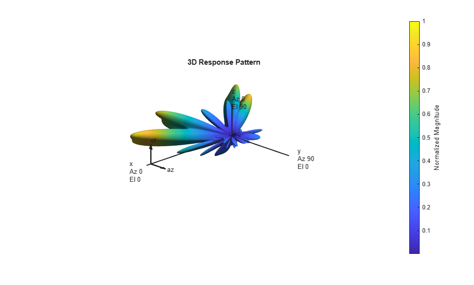
For the wideband OFDM system modeled, the analog weights, mFrf, are the averaged weights over the multiple subcarriers. The array response pattern shows distinct data streams represented by the stronger lobes. These lobes indicate the spread or separability achieved by beamforming. The Introduction to Hybrid Beamforming example compares the patterns realized by the optimal, fully digital approach, with those realized from the selected hybrid approach, for a single-user system.
Data Transmission
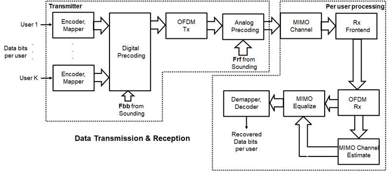
Next, we configure the system's data transmitter. This processing includes channel coding, bit mapping to complex symbols, splitting of the individual data stream to multiple transmit streams, baseband precoding of the transmit streams, OFDM modulation with pilot mapping and RF analog beamforming for all the transmit antennas employed.
% Convolutional encoder
encoder = comm.ConvolutionalEncoder( ...
    'TrellisStructure',poly2trellis(7,[133 171 165]), ...
    'TerminationMethod','Terminated');

txDataBits = cell(numUsers, 1);
gridData = complex(zeros(prm.numCarriers,prm.numDataSymbols,numSTS));
for uIdx = 1:numUsers
    % Generate mapped symbols from bits per user
    txDataBits{uIdx} = randi([0,1],prm.numFrmBits(uIdx),1);
    encodedBits = encoder(txDataBits{uIdx});

    % Bits to QAM symbol mapping
    mappedSym = qammod(encodedBits,prm.modMode,'InputType','bit', ...
    'UnitAveragePower',true);

    % Map to layers: per user, per symbol, per data stream
    stsIdx = sum(numSTSVec(1:(uIdx-1)))+(1:numSTSVec(uIdx));
    gridData(:,:,stsIdx) = reshape(mappedSym,prm.numCarriers, ...
        prm.numDataSymbols,numSTSVec(uIdx));
end

% Apply normalized precoding weights to the subcarriers, assuming perfect feedback
P = complex(zeros(numSTS,numSTS,prm.numCarriers));
for carrIdx = 1:prm.numCarriers
    Q = squeeze(v(carrIdx,:,:));
    normQ = Q * sqrt(numTx)/norm(Q,'fro');  % normalize
    P(:,:,carrIdx) = normQ;
end
preData = ofdmPrecode(gridData,P);

% Multi-antenna pilots
pilots = helperGenPilots(prm.numDataSymbols,numSTS);

% OFDM modulation of the data
txOFDM = ofdmmod(preData,prm.FFTLength,prm.CyclicPrefixLength,...
                 prm.NullCarrierIndices,prm.PilotCarrierIndices,pilots);
%   scale power for used sub-carriers
txOFDM = txOFDM * (prm.FFTLength/ ...
    sqrt((prm.FFTLength-length(prm.NullCarrierIndices))));

% Generate preamble with the feedback weights and prepend to data
[preambleSigD, pilotsymD] = helperGenPreamble(prm,v);
cfgD = ofdmPilotConfig(FFTLength = prm.FFTLength, NumGuardBandCarriers = [7;6], NumSymbols = prm.numSTS, ...
                       NumTransmitStreams = prm.numSTS, StreamGroups = {1:prm.numSTS}, ...
                       PilotLocations = {ofdmPilotGrid(1,1:prm.numSTS,prm.CarriersLocations,1)}, ...
                       PilotSymbols = {permute(pilotsymD(prm.CarriersLocations,:,:),[2 3 1])});
validate(cfgD);

txSigSTS = [preambleSigD;txOFDM];

% RF beamforming: Apply Frf to the digital signal
%   Each antenna element is connected to each data stream
txSig = txSigSTS*mFrf;
For the selected, fully connected RF architecture, each antenna element uses prm.numSTS analog gains, as given by the individual columns of the mFrf matrix.
The processing for the data transmission and reception modeled is shown below.
Signal Propagation
The example offers an option for spatial MIMO channel and a simpler static-flat MIMO channel for validation purposes.
The scattering model uses a single-bounce ray tracing approximation with a parametrized number of scatterers. For this example, the number of scatterers is set to 50. The 'Scattering' option models the scatterers placed randomly within a sphere around the receiver, similar to the one-ring model [ 6 ].
The channel models allow path-loss modeling and both line-of-sight (LOS) and non-LOS propagation conditions. The example assumes non-LOS propagation and isotropic antenna element patterns with linear or rectangular geometry.
% Apply a spatially defined channel to the transmit signal
[rxSig,chanDelay] = helperApplyMUChannel(txSig,prm,spLoss,preambleSig);
The same channel is used for both sounding and data transmission. The data transmission has a longer duration and is controlled by the number of data symbols parameter, prm.numDataSymbols. The channel evolution between the sounding and transmission stages is modeled by prepending the preamble signal to the data signal. The preamble primes the channel to a valid state for the data transmission, and is ignored from the channel output.
For a multi-user system, independent channels per user are modeled.
Receive Amplification and Signal Recovery
The receiver modeled per user compensates for the path loss by amplification and adds thermal noise. Like the transmitter, the receiver used in a MIMO-OFDM system contains many stages including OFDM demodulation, MIMO equalization, QAM demapping, and channel decoding.
hfig = figure('Name','Equalized symbol constellation per stream');
scFact = ((prm.FFTLength-length(prm.NullCarrierIndices))...
         /prm.FFTLength^2)/numTx;
nVar = noisepow(prm.chanSRate,prm.NFig,290)/scFact;
decoder = comm.ViterbiDecoder('InputFormat','Unquantized', ...
    'TrellisStructure',poly2trellis(7, [133 171 165]), ...
    'TerminationMethod','Terminated','OutputDataType','double');

for uIdx = 1:numUsers
    stsU = numSTSVec(uIdx);
    stsIdx = sum(numSTSVec(1:(uIdx-1)))+(1:stsU);

    % Front-end amplifier gain and thermal noise
    rxPreAmp = phased.ReceiverPreamp( ...
        'Gain',spLoss(uIdx), ...        % account for path loss
        'NoiseFigure',prm.NFig,'ReferenceTemperature',290, ...
        'SampleRate',prm.chanSRate);
    rxSigAmp = rxPreAmp(rxSig{uIdx});

    % Scale power for occupied sub-carriers
    rxSigAmp = rxSigAmp*(sqrt(prm.FFTLength-length(prm.NullCarrierIndices)) ...
        /prm.FFTLength);

    % OFDM demodulation
    rxOFDM = ofdmdemod(rxSigAmp(chanDelay(uIdx)+1: ...
        end-(prm.numPadZeros-chanDelay(uIdx)),:),prm.FFTLength, ...
        prm.CyclicPrefixLength,prm.CyclicPrefixLength);

    % Channel estimation from the mapped preamble
    hEst = ofdmChannelEstimate(rxOFDM((cfgD.NumGuardBandCarriers(1)+1):(cfgD.FFTLength - cfgD.NumGuardBandCarriers(2)),1:numSTS,:),...
                               cfgD,prm.CyclicPrefixLength,"Algorithm","leastsquares");
    hD = squeeze(hEst(prm.CarriersLocations-cfgD.NumGuardBandCarriers(1),1,:,:));

    % MIMO equalization
    %   Index into streams for the user of interest
    [rxEq,CSI] = ofdmEqualize(rxOFDM(prm.CarriersLocations,numSTS+1:end,:),hD(:,stsIdx,:),'Algorithm','zf');

    % Soft demodulation
    rxSymbs = rxEq(:)/sqrt(numTx);
    rxLLRBits = qamdemod(rxSymbs,prm.modMode,'UnitAveragePower',true, ...
        'OutputType','approxllr','NoiseVariance',nVar);

    % Apply CSI prior to decoding
    rxLLRtmp = reshape(rxLLRBits,prm.bitsPerSubCarrier,[], ...
        prm.numDataSymbols,stsU);
    csitmp = reshape(CSI,1,[],1,numSTSVec(uIdx));
    rxScaledLLR = rxLLRtmp.*csitmp;

    % Soft-input channel decoding
    rxDecoded = decoder(rxScaledLLR(:));

    % Decoded received bits
    rxBits = rxDecoded(1:prm.numFrmBits(uIdx));

    % Plot equalized symbols for all streams per user
    scaler = 2;
    for i = 1:stsU
        subplot(numUsers, max(numSTSVec), (uIdx-1)*max(numSTSVec)+i);
        plot(reshape(rxEq(:,:,i)/sqrt(numTx), [], 1), '.');
        axis square
        xlim(gca,[-scaler scaler]);
        ylim(gca,[-scaler scaler]);
        title(['U' num2str(uIdx) ', G' num2str(prm.groups(uIdx)) ', DS' num2str(i)]);
        grid on;
    end

    % Compute and display the EVM
    evm = comm.EVM('Normalization','Average constellation power', ...
        'ReferenceSignalSource','Estimated from reference constellation', ...
        'ReferenceConstellation', ...
        qammod((0:prm.modMode-1)',prm.modMode,'UnitAveragePower',1));
    rmsEVM = evm(rxSymbs);
    disp(['User ' num2str(uIdx) ' (Group ' num2str(prm.groups(uIdx)) ')']);
    disp(['  RMS EVM (%) = ' num2str(rmsEVM)]);

    % Compute and display bit error rate
    ber = comm.ErrorRate;
    measures = ber(txDataBits{uIdx},rxBits);
    fprintf('  BER = %.5f; No. of Bits = %d; No. of errors = %d\n', ...
        measures(1),measures(3),measures(2));
end
User 1 (Group 1)
  RMS EVM (%) = 0.00090417
  BER = 0.00000; No. of Bits = 12474; No. of errors = 0
User 2 (Group 1)
  RMS EVM (%) = 0.0010672
  BER = 0.00000; No. of Bits = 9354; No. of errors = 0
User 3 (Group 1)
  RMS EVM (%) = 0.00094048
  BER = 0.00000; No. of Bits = 6234; No. of errors = 0
User 4 (Group 2)
  RMS EVM (%) = 0.00095598
  BER = 0.00000; No. of Bits = 12474; No. of errors = 0
User 5 (Group 2)
  RMS EVM (%) = 0.00096486
  BER = 0.00000; No. of Bits = 9354; No. of errors = 0
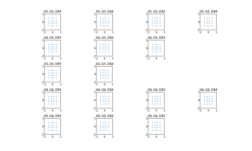
For the MIMO system modeled, the displayed receive constellation of the equalized symbols offers a qualitative assessment of the reception. The actual bit error rate offers the quantitative figure by comparing the actual transmitted bits with the received decoded bits per user.
rng(s); % restore RNG state
Conclusion and Further Exploration
The example highlights the use of hybrid beamforming for multi-user MIMO-OFDM systems. It allows you to explore different system configurations for a variety of channel models by changing a few system-wide parameters.
The set of configurable parameters includes the number of users, number of data streams per user, number of transmit/receive antenna elements, array locations, and channel models. Adjusting these parameters, you can study the parameters' individual or combined effects on the overall system. As examples, vary:
the number of users and corresponding data streams,
prm.numSTSVec, and their corresponding group,prm.groups, to switch between multi-user and single-user systems, orthe channel type,
prm.ChanType, orthe number of rays,
prm.nRays, used for a single-user system, orthe JSDM feedback type,
prm.jsdmType, and the group locations,groupAnglesandgroupRanges, used in the multi-user system.
Explore the following helper functions used by the example:
helperApplyMUChannel.mhelperArrayInfo.mhelperGetCovariance.mhelperGenPreamble.mhelperGenPilots.mhelperGetHeff.mhelperGetP.m
To see JSDM used in a 5G communications system, see the TDD Reciprocity-Based PDSCH MU-MIMO Using SRS (5G Toolbox) example.
References
Molisch, A. F., et al. "Hybrid Beamforming for Massive MIMO: A Survey." IEEE® Communications Magazine, Vol. 55, No. 9, September 2017, pp. 134-141.
Li Z., S. Han, and A. F. Molisch. "Hybrid Beamforming Design for Millimeter-Wave Multi-User Massive MIMO Downlink." IEEE ICC 2016, Signal Processing for Communications Symposium.
El Ayach, Oma, et al. "Spatially Sparse Precoding in Millimeter Wave MIMO Systems." IEEE Transactions on Wireless Communications, Vol. 13, No. 3, March 2014, pp. 1499-1513.
Adhikary A., J. Nam, J-Y Ahn, and G. Caire. "Joint Spatial Division and Multiplexing - The Large-Scale Array Regime." IEEE Transactions on Information Theory, Vol. 59, No. 10, October 2013, pp. 6441-6463.
Spencer Q., A. Swindlehurst, M. Haardt, "Zero-Forcing Methods for Downlink Spatial Multiplexing in Multiuser MIMO Channels." IEEE Transactions on Signal Processing, Vol. 52, No. 2, February 2004, pp. 461-471.
Shui, D. S., G. J. Foschini, M. J. Gans and J. M. Kahn. "Fading Correlation and its Effect on the Capacity of Multielement Antenna Systems." IEEE Transactions on Communications, Vol. 48, No. 3, March 2000, pp. 502-513.