workspaceGoalRegion
Define workspace region of end-effector goal poses
Description
The workspaceGoalRegion object defines a region for valid
end-effector goal poses. To sample poses within the bounds of the goal region, use the
sample object function. You can also visualize the bounds you define
using the show object function.
The object is typically used with rapidly exploring random tree (RRT) planners like the
manipulatorRRT
object. The sample generates alternative goal states to increase the
likelihood of finding valid paths.
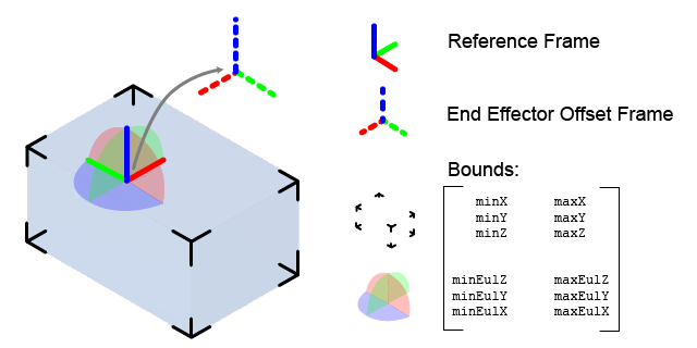
The key elements of the goal region are defined as object properties:
ReferencePose — Pose of the reference frame in the world frame. The bounds and offset pose are relative to this frame.
EndEffectorOffsetPose — Offset pose applied to any pose sampled in the reference frame. Use this offset if the end effector needs to be positioned differently based on grasping or other geometric restrictions.
Bounds — Bounds of the region as a 6-by-2 matrix with the minimum and maximum values for the XYZ-position and ZYX Euler angle orientation, in respective column vectors.
Creation
Syntax
Description
goalRegion = workspaceGoalRegion(EndEffectorName)EndEffectorName property.
goalRegion = workspaceGoalRegion(EndEffectorName,Name,Value)workSpaceGoalRegion("endEffector","Bounds",limits) creates a
workspace goal region with the Bounds property specified as
a matrix.
Properties
Object Functions
Examples
Specify a goal region in your workspace and plan a path within those bounds. The workspaceGoalRegion object defines the bounds on the xyz-position and zyx Euler orientation of the robot end effector. The manipulatorRRT object plans a path based on that goal region and samples random poses within the bounds.
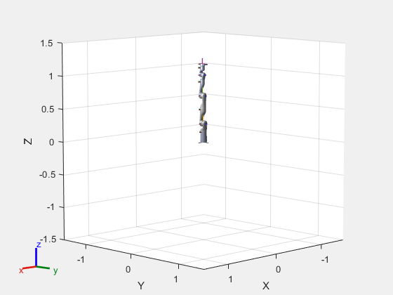
Load an existing robot model as a rigidBodyTree object.
robot = loadrobot("kinovaGen3", "DataFormat", "row");
ax = show(robot);
Create Path Planner
Create a rapidly-exploring random tree (RRT) path planner for the robot. This example uses an empty environment, but this workflow also works well with cluttered environments. You can add collision objects to the environment like the collisionBox or collisionMesh object.
planner = manipulatorRRT(robot,{});
planner.SkippedSelfCollisions="parent";
Define Goal Region
Create a workspace goal region using the end-effector body name of the robot.
Define the goal region parameters for your workspace. The goal region includes a reference pose, xyz-position bounds, and orientation limits on the zyx Euler angles. This example specifies bounds on the xy-plane in meters and allows rotation about the z-axis in radians.
goalRegion = workspaceGoalRegion(robot.BodyNames{end});
goalRegion.ReferencePose = trvec2tform([0.5 0.5 0.2]);
goalRegion.Bounds(1, :) = [-0.2 0.2];    % X Bounds
goalRegion.Bounds(2, :) = [-0.2 0.2];    % Y Bounds
goalRegion.Bounds(4, :) = [-pi/2 pi/2];  % Rotation about the Z-axis
You can also apply a fixed offset to all poses sampled within the region. This offset can account for grasping tools or variations in dimensions within your workspace. For this example, apply a fixed transformation that places the end effector 5 cm above the workspace.
goalRegion.EndEffectorOffsetPose = trvec2tform([0 0 0.05]);
hold on
show(goalRegion);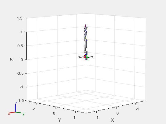
Plan Path To Goal Region
Plan a path to the goal region from the robot's home configuration. Due to the randomness in the RRT algorithm, this example sets the rng seed to ensure repeatable results.
rng(0)
path = plan(planner,homeConfiguration(robot),goalRegion);
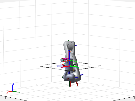
Show the robot executing the path. To visualize a more realistic path, interpolate points between path configurations.
interpConfigurations = interpolate(planner,path,5);

for i = 1:size(interpConfigurations,1)
    show(robot,interpConfigurations(i,:),"PreservePlot",false);
    set(ax,'ZLim',[-0.05 0.75],'YLim',[-0.05 1],'XLim',[-0.05 1],...
        'CameraViewAngle',5)

    drawnow
end
hold off
Adjust End-Effector Pose
Notice that the robot arm approaches the workspace from the bottom. To flip the orientation of the final position, add a pi rotation to the Y-axis for the reference pose.
goalRegion.EndEffectorOffsetPose = ...
    goalRegion.EndEffectorOffsetPose*eul2tform([0 pi 0],"ZYX");
Replan the path and visualize the robot motion again. The robot now approaches from the top.
hold on
show(goalRegion);
path = plan(planner,homeConfiguration(robot),goalRegion);

interpConfigurations = interpolate(planner,path,5);

for i = 1 : size(interpConfigurations,1)
    show(robot, interpConfigurations(i, :),"PreservePlot",false);
    set(ax,'ZLim',[-0.05 0.75],'YLim',[-0.05 1],'XLim',[-0.05 1])
    drawnow;
end
hold off

References
[1] Berenson, Dmitry, Siddhartha S. Srinivasa, Dave Ferguson, Alvaro Collet, and James J. Kuffner. "Manipulation Planning with Workspace Goal Regions." In 2009 IEEE International Conference on Robotics and Automation (ICRA), 618–24. Kobe, Japan: Institute of Electrical and Electronics Engineers, 2009. https://doi.org/10.1109/ROBOT.2009.5152401.
Extended Capabilities
Version History
Introduced in R2021a
See Also
manipulatorRRT | sample | show