Export ASAP2 File for Data Measurement and Calibration
Generate ASAP2 and CDF Calibration Files (Embedded Coder) is recommended way of generating the ASAP2 file, because it allows you to generate the latest version of ASAP2 file as per ASAM standards and provides the Generate Calibration Files tool.
Generation of ASAP2 File Using Generate Calibration Files Tool
Open Generate Calibration Files Tool
Open the model.
Open the Embedded Coder app.
Generate code for the model.
On the C Code tab, select Share > Generate Calibration Files.
Note
For AUTOSAR models, select Autosar > Share > Generate Calibration Files.
Using the tool, you can generate A2L and cdfx
files at the same
time for a model. You can use the tool for models configured with an ERT-based, GRT-based,
Simulink Real-Time, Classic AUTOSAR, or Adaptive AUTOSAR system target file. The tool
remembers the last used settings, such as the version of the ASAP2 file, include or
exclude comments, turn off or on the ASAP2 file and CDF file generation. Simulink saves
these settings in the MATLAB preferences. The settings will override the default
settings.
For Adaptive AUTOSAR and Simulink Real-Time system target files, you can generate the ASAP2 file for the C++ language. For GRT- and ERT- based system target files, you can generate an ASAP2 file only for C.
For classic AUTOSAR models, the tool allows you to include or exclude RTE elements into the ASAP2 file by using the Include AUTOSAR RTE elements option.
ASAP2 File Generation
ASAP2 defines the description format of the internal ECU variables used for tuning parameters and measuring signal data as an application executes. To generate an ASAP2 file:
By default the Generate ASAP2 option is enabled. If it is not enabled, slide the Generate ASAP2 slider to the on position to enable A2L generation.
To change the name of the A2L file, in the File name field, specify the name.
By default, the code generator uses the build folder for the folder path of the selected model. If you want to specify a different folder path for the A2L file, you can do that in the Folder path field.
To replace ECU addresses in the A2L file, in the Symbol file field, provide a symbol file associated with the application executable. Otherwise, clear the Address replacement field.
The tool supports an ELF, PDB, DWARF, or executable file as a symbol file to replace the ECU addresses.
Set Version to the required version of the A2L file to be generated. The default version is 1.71.
To exclude comments in the A2L file, clear Include comments.
For Classic AUTOSAR models, to exclude RTE elements in the A2L file, clear Include AUTOSAR RTE elements.
Click Generate.
To generate the A2L file programmatically, use the coder.asap2.export
function.
Generation of ASAP2 File Using ASAP2Interface Parameter
The ASAP2Interface
parameter is not present in the configuration
parameters anymore. In a coming release the parameter will be completely removed. You can
generate the ASAP2 file using Generate Calibration Files tool, or coder.asap2.export
(Embedded Coder)
function. For more information, see Generate ASAP2 and CDF Calibration Files (Embedded Coder).
The ASAM MCD-2 MC standard, also known as ASAP2, is a data definition standard proposed
by the Association for Standardization of Automation and Measuring Systems (ASAM). ASAP2 is
a non-object-oriented description of the data used for measurement, calibration, and
diagnostic systems. For more information on ASAM and the ASAM MCD-2 MC (ASAP2) standard, see
the ASAM website at www.asam.net
.
The code generator enables you to export an ASAP2 file containing information about your model during the code generation process.
Simulink® Coder™ support for ASAP2 file generation is version-neutral. By default, the software generates ASAP2 version 1.31 format, but the generated model information is generally compatible with other ASAP2 versions. ASAP2 file generation is also neutral with respect to the specific needs of ASAP2 measurement and calibration tools. The software provides customization APIs that you can use to customize ASAP2 file generation to generate an ASAP2 version and to meet the specific needs of your ASAP2 tools.
What You Should Know
To make use of ASAP2 file generation, you should become familiar with:
ASAM and the ASAP2 standard and terminology. See the ASAM Web site at
www.asam.net
.Configuring model data elements for code generation. See Code Mappings Editor – C.
Storage and representation of signals and parameters in generated code. See Data Representation in Generated Code.
If you have Embedded Coder®, see Data Representation in Generated Code (Embedded Coder).
System Target Files Supporting ASAP2
You can use ASAP2 file generation with varying system target file configurations. For example, GRT- and ERT- based configurations enables you to generate an ASAP2 file as part of the code generation and build process.
For Adaptive AUTOSAR target and Simulink Real-Time targets, you can generate the ASAP2 file for C++ language. For ERT and GRT targets, you can generate ASAP2 file only for language C and language C++ is not supported.
For procedures for generating ASAP2 files by using the system target file configurations, see ASAP2 interface.
Define ASAP2 Information
Define ASAP2 Information for Parameters and Signals. The ASAP2 file generation process requires information about parameters and signals in your model. Some of this information is contained in the model itself. Use Simulink data objects in a workspace or data dictionary to complete the ASAP2 file generation process. In some cases, the use of workspace objects is optional.
Use the Model Data Editor and built-in Simulink data objects to provide information, such as using
Simulink.Signal
objects to provide MEASUREMENT information and
Simulink.Parameter
objects to provide CHARACTERISTIC information.
You can use data objects from data classes that are derived from
Simulink.Signal
and Simulink.Parameter
to
provide the information. See Data Objects and Model Data
Editor.
This table contains the minimum set of data attributes required for ASAP2 file
generation. Some data attributes are defined in the model. Others attributes are
supplied in the properties of objects. For attributes that are defined in
Simulink.Signal
or Simulink.Parameter
objects,
the table lists the associated property name.
Data Attribute | Defined In | Property Name |
---|---|---|
Name (symbol) | Model and data object | Inherited from the handle of the data object to which parameter or signal name resolves |
Description | Data object |
|
Data type | Model or data object |
|
Scaling | Model or data object | DataType |
Minimum allowable value | Model or data object |
|
Maximum allowable value | Model or data object |
|
Unit | Model or data object |
|
Memory address (optional) | Model or data object |
|
Memory Address Attribute. If the memory address attribute is unknown before code generation, the code
generator inserts ECU Address
placeholder text in the generated ASAP2
file. You can substitute an actual address for the placeholder by postprocessing the
generated file. For an example, see the file
. matlabroot
/toolbox/rtw/targets/asap2/asap2/asap2post.masap2post.m
parses through the
linker map file that you provide and replaces the ECU Address
placeholders in the ASAP2 file with the actual memory addresses. Because linker map
files vary from compiler to compiler, you might need to modify the regular expression
code in asap2post.m
to match the format of the linker map that you
use.
If you have Embedded Coder installed on your system, and if you are generating Executable and
Linkable Format (ELF) or Program Database (PDB) files for your embedded target, you can
use the rtw.asap2SetAddress
function to automate ECU address
replacement. For more information, see Automatic ECU Address Replacement for ASAP2 Files (Embedded Coder) (Embedded Coder).
If the memory address attribute is known before code generation, it can be defined
in the data item or data object. By default, the MemoryAddress_ASAP2
property does not exist in the Simulink.Signal
or
Simulink.Parameter
data object classes. If you want to add the
attribute, add a property called MemoryAddress_ASAP2
to a custom
class that is a subclass of the Simulink
or ASAP2
class. For information on subclassing Simulink data classes, see Define Data Classes.
This table indicates the Simulink object properties that have replaced the ASAP2 object properties of the previous release.
Differences Between ASAP2 and Simulink Parameter and Signal Object Properties
ASAP2 Object Properties (Previous) | Simulink Object Properties (Current) |
---|---|
LONGID_ASAP2 | Description |
PhysicalMin_ASAP2 | Min |
PhysicalMax_ASAP2 | Max |
Units_ASAP2 | Unit |
Automatic ECU Address Replacement for ASAP2 Files (Embedded Coder). If you have Embedded Coder installed on your system, and if you are generating Executable and
Linkable Format (ELF) or Program Database (PDB) files for your embedded target, you can
use the rtw.asap2SetAddress
function to automate the replacement of
ECU Address
placeholder memory address values with actual addresses
in the generated ASAP2 file.
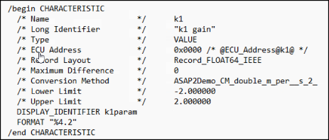
If the memory address attribute is unknown before code generation, the code
generator inserts ECU Address
placeholder text in the generated ASAP2
file, as shown
/begin CHARACTERISTIC /* Name */ Ki /* Long Identifier */ "" /* Type */ VALUE /* ECU Address */ 0x0000 /* @ECU_Address@Ki@ */
To substitute actual addresses for the ECU Address
placeholders,
process the generated ASAP2 file by using the rtw.asap2SetAddress
function. The syntax is:
rtw.asap2SetAddress(ASAP2File,InfoFile)
The arguments are character vectors specifying the name of the generated ASAP2 file
and the name of the generated executable ELF file, PDB file from Microsoft toolchain, or
DWARF debug information files for the model. When called,
rtw.asap2SetAddress
extracts the actual ECU address from the
specified ELF, PDB, or DWARF file and replaces the placeholder in the ASAP2 file with
the actual address, for example:
/begin CHARACTERISTIC /* Name */ Ki /* Long Identifier */ "" /* Type */ VALUE /* ECU Address */ 0x40009E60
Define ASAP2 Information for Lookup Tables. Simulink
Coder software generates ASAP2 descriptions for lookup table data and its
breakpoints. The software represents 1-D table data as CURVE
information, 2-D table data as MAP
information, and breakpoints as
AXIS_DESCR
and AXIS_PTS
information. You can
model lookup tables by using one of the following Simulink Lookup Table blocks:
Interpolation Using Prelookup — 1 and 2 dimensions
1–D Lookup Table
2–D Lookup Table
n-D Lookup Table — 1 and 2 dimensions
The software supports these types of lookup table breakpoints (axis points).
Breakpoint Type | Information Generated |
---|---|
Tunable and shared among multiple table axes (common axis) |
|
Fixed and nontunable (fixed axis) | One of these variants of
|
Tunable but not shared among multiple tables (standard axis) |
|
When you configure the blocks for ASAP2 code generation:
For table data, use a
Simulink.Parameter
data object with a non-Auto
storage class.For tunable breakpoint data that is shared among multiple table axes (
COM_AXIS
), use aSimulink.Parameter
data object that has a non-Auto
storage class.For fixed, nontunable breakpoint data (
FIX_AXIS
), use workspace variables or arrays specified in the block parameters dialog box. The breakpoints must be stored as integers in the code. The data type must be a built-in integer type (int8
,int16
,int32
,uint8
,uint16
, oruint32
), a fixed-point data type, or an equivalent alias type.For tunable breakpoint data that is not shared among multiple tables (STD_AXIS):
Create a
Simulink.Bus
object to define thestruct
packaging (names and order of the fields). The fields of the parameter structure must correspond to the lookup table data and each axis of the lookup table block. For example, in an n-D Lookup Table block that has 2 dimensions, the structure must contain only three fields. This bus object describes the record layout for the lookup characteristic.Create a
Simulink.Parameter
object to represent a tunable parameter.Create table and axis values.
Optionally, specify the Units, Minimum, and Maximum properties for the parameter object.
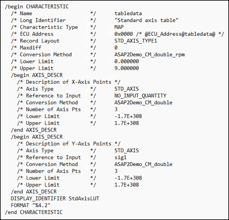
Here is an example of an n-D Lookup Table record generated into an ASAP2 file in Standard Axis format:
/begin CHARACTERISTIC /* Name */ STDAxisParam ... /* Record Layout */ Lookup1D_X_WORD_Y_FLOAT32_IEEE ... begin AXIS_DESCR /* Description of X-Axis Points */ /* Axis Type */ STD_AXIS ... /end AXIS_DESCR /end CHARACTERISTIC /begin RECORD_LAYOUT Lookup1D_X_WORD_Y_FLOAT32_IEEE AXIS_PTS_X 1 WORD INDEX_INCR DIRECT FNC_VALUES 2 FLOAT32_IEEE COLUMN_DIR DIRECT /end RECORD_LAYOUT
Generate an ASAP2 File
Generating ASAP2 Files. Use the Generic Real-Time system target file or a Embedded Coder system target file to generate an ASAP2 file as part of the code generation and build process.
Generate ASAP2 file by using the system target files that have built-in ASAP2 support.
Use GRT- or ERT- Based System Target File. To generate the ASAP2 data definition for a model by using a Generic Real-Time(GRT) system target file or Embedded Coder system target file:
Use the Code Mappings Editor – C to apply storage classes to signals, block states, and model parameters, as described in C Data Code Interface Configuration for Model Interface Elements.
Parameters are not represented in the ASAP2 file if one or more of the following conditions exist:
You apply storage class
Auto
,FileScope
,Struct
, orDefault
(throughModel default
).You apply storage class through
Embedded Coder Dictionary
.You apply a storage class that causes the code generator to generate a macro or non-addressable variable.
Use the Property Inspector to configure the remaining storage class properties for each data element.
Set the model configuration parameter System target file to a GRT- or ERT- based system target file.
Enable the configuration parameter ASAP2 interface with the command
set_param('model_Name','GenerateASAP2',true);
Note
You can no longer enable generation of ASAP2 files from the Model Configuration Parameter dialog box. As Generate ASAP2 and CDF Calibration Files describes, use the
Generate Calibration Files
tool, or use the command line model configuration parameterGenerateASAP2
.Select parameter Generate code only.
Click Apply.
Generate code.
The code generator writes the ASAP2 file to the build folder. By default, the file is named
, wheremodel
.a2l
is the name of the model. The ASAP2 setup file controls the ASAP2 file name. For details, see Customize Generated ASAP2 File.model
Generate ASAP2 Files for Referenced Models. The build process can generate an ASAP2 file for each referenced model in a model reference hierarchy. In the generated ASAP2 file, MEASUREMENT records represent signals and states inside the referenced model.
To generate ASAP2 files for referenced models, select ASAP2 file generation for the top model and for each referenced model in the reference hierarchy.
Merge ASAP2 Files for Top and Referenced Models. Use function rtw.asap2MergeMdlRefs
to merge the ASAP2 files
generated for top and referenced models. The function has this syntax:
[status,info] = rtw.asap2MergeMdlRefs(topModelName,asap2FileName)
topModelName
is the name of the model containing one or more referenced models.asap2FileName
is the name that you specify for the merged ASAP2 file.Optional:
status
returns false (logical 0) if the merge completed and returns true (logical 1) otherwise.Optional:
info
returns additional information about merge failure ifstatus
is true. Otherwise, it returns an empty character vector.
Consider the following example.
[status,info] = rtw.asap2MergeMdlRefs('myTopMdl','merged.a2l')
myTopMdl
and its referenced models in the file merged.a2l
.Structure of ASAP2 File
This table outlines the basic structure of the ASAP2 file and describes the Target Language Compiler (TLC) functions and files used to create each part of the file:
Static parts of the ASAP2 file are shown in bold.
Function calls are indicated by
%<FunctionName()>
.
File Section | Contents of asap2main.tlc | TLC File Containing Function Definition |
---|---|---|
File header |
|
|
|
|
|
|
|
|
|
|
|
|
|
|
|
|
|
Model-dependent |
|
|
|
|
|
|
|
|
|
|
|
|
| |
File footer/tail |
|
|