Configure Model, Generate Code, and Simulate
About This Example
Learning Objectives
Learn about the functional behavior of the example model.
Learn about the role of the example test harness and its components.
Run simulation tests on a model.
Prerequisites
Ability to open and modify Simulink® models and subsystems.
Understand subsystems and how to view subsystem details.
Understand referenced models and how to view referenced model details.
Ability to set model configuration parameters.
View the Top Model
This example uses a simple, but functionally complete, example model of a throttle controller. The model features redundant control algorithms. The model highlights a standard model structure and a set of basic blocks in algorithm design.
Open ThrottleControl. Note that this model uses Stateflow® software.
open_system ('ThrottleControl')

The top level of the model consists of the following elements:
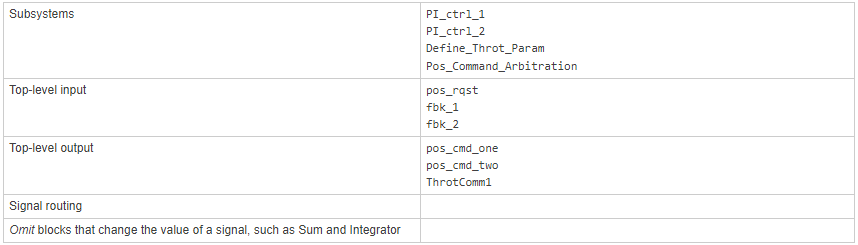
The layout uses a basic architectural style for models:
Separation of calculations from signal routing (lines and buses)
Partitioning into subsystems
You can apply this style to a wide range of models
View the Subsystems
Two subsystems in the top model represent proportional-integral (PI) controllers, PI_ctrl_1 and PI_ctrl_2. At this stage, these identical subsystems, use identical data.
1. Open the PI_ctrl_1 subsystem.
open_system('ThrottleControl/PI_ctrl_1')
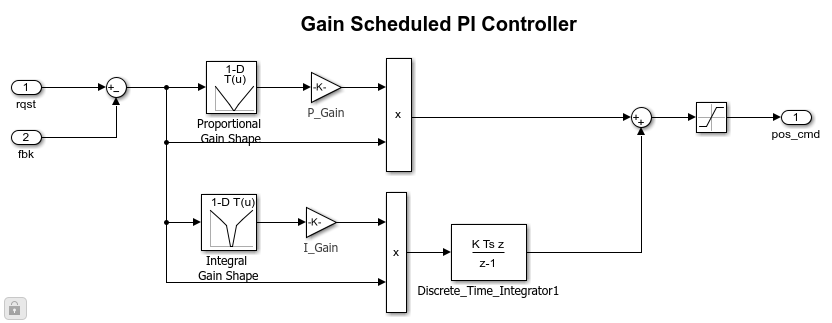
The PI controllers in the model are from a library, a group of related blocks or models for reuse. Libraries provide one of two methods for including and reusing models. The second method, model referencing, is described below. You cannot edit a block that you add to a model from a library. Edit the block in the library so that instances of the block in different models remain consistent.
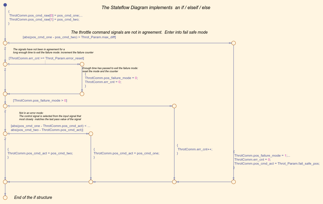
2. Open the Pos_Command_Arbitration system. This Stateflow chart performs basic error checking on the two command signals. If the command signals are too far apart, the Stateflow diagram sets the output to a fail_safe position.
open_system('ThrottleControl/Pos_Command_Arbitration')
Simulation Test Environment
To test the throttle controller algorithm, incorporate it into a test harness. A test harness is a model that evaluates the control algorithm and offers the following benefits:
Separates test data from the control algorithm.
Separates the plant or feedback model from the control algorithm.
Provides a reusable environment for multiple versions of the control algorithm.
The test harness model for this example implements a common simulation testing environment consisting of the following parts:
Unit under test
Test vector source
Evaluation and logging
Plant or feedback system
Input and output scaling
1. Open the test harness model ThrottleControlTestHarness.
open_system('ThrottleControlTestHarness')
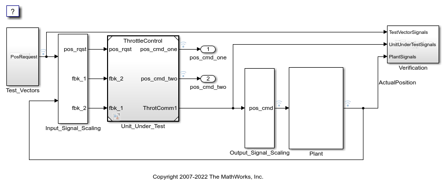
The ThrottleControl model is set up as the control algorithm of the test harness. You can see this configuration by right-clicking the Unit_Under_Test block and selecting Block Parameters (ModelReference).

The control algorithm is the unit under test, as indicated by the name of the Model block, Unit_Under_Test.
The Model block provides a method for reusing components. From the top model, it allows you to reference other models (directly or indirectly) as compiled functions. By default, Simulink software recompiles the model when the referenced models change. Compiled functions have the following advantages over libraries:
Simulation time is faster for large models.
You can directly simulate compiled functions.
Simulation requires less memory. Only one copy of the compiled model is in memory, even when the model is referenced multiple times.
2. Open the test vector source, implemented in this test harness as the Test_Vectors subsystem.
open_system('ThrottleControlTestHarness/Test_Vectors')

The subsystem uses a Signal Editor block for the test vector source. The block has data that drives the simulation (PosRequest) and provides the expected results used by the Verification subsystem. This example test harness uses only one set of test data. Typically, create a test suite that fully exercises the system.
3. Open the evaluation and logging subsystem, implemented in this test harness as subsystem Verification.
open_system('ThrottleControlTestHarness/Verification')
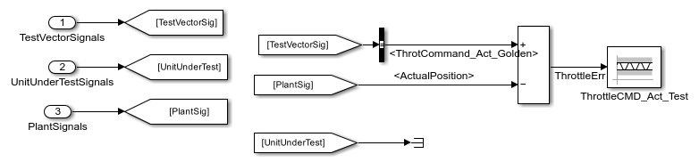
A test harness compares control algorithm simulation results against golden data - test results that exhibit the desired behavior for the control algorithm as certified by an expert. In the Verification subsystem, an Assertion block compares the simulated throttle value position from the plant against the golden value from the test harness. If the difference between the two signals is greater than 5%, the test fails and the Assertion block stops the simulation.
Alternatively, you can evaluate the simulation data after the simulation completes execution. Perform the evaluation with either MATLAB® scripts or third-party tools. Post-execution evaluation provides greater flexibility in the analysis of data. However, it requires waiting until execution is complete. Combining the two methods can provide a highly flexible and efficient test environment.
4. Open the plant or feedback system, implemented in this test harness as the Plant subsystem.
open_system('ThrottleControlTestHarness/Plant')

The Plant subsystem models the throttle dynamics with a transfer function in canonical form. You can create plant models to varying levels of fidelity. It is common to use different plant models at different stages of testing.
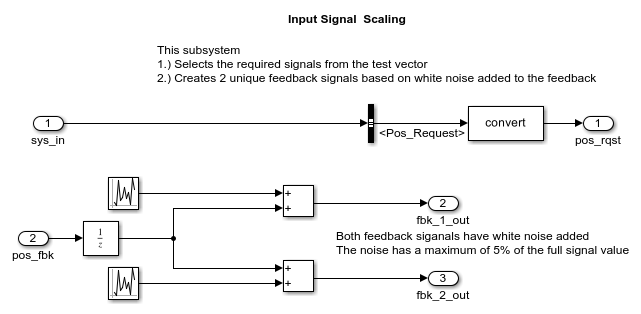
5. Open the input and output scaling subsystems, implemented in this test harness as Input_Signal_Scaling and Output_Signal_Scaling.
open_system('ThrottleControlTestHarness/Input_Signal_Scaling')
open_system('ThrottleControlTestHarness/Output_Signal_Scaling')
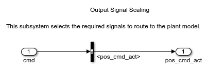
The subsystems that scale input and output perform the following primary functions:
Select input signals to route to the unit under test.
Select output signals to route to the plant.
Rescale signals between engineering units and units that are writable for the unit under test.
Handle rate transitions between the plant and the unit under test.
Run Simulation Tests
Start a test harness model simulation. When the simulation is complete, the following results appear.

The lower-right hand plot shows the difference between the expected (golden) throttle position and the throttle position that the plant calculates. If the difference between the two values is greater than plus or minus 0.05, the simulation stops.
Key Points
A basic model architecture separates calculations from signal routing and partitions the model into subsystems.
Two options for model reuse include block libraries and model referencing.
If you represent your control algorithm in a test harness as a Model block, specify the name of the control algorithm model in the Model Reference Parameters dialog box.
A test harness is a model that evaluates a control algorithm. Typically, a harness consists of a unit under test, a test vector source, evaluation and logging, a plant or feedback system, and input and output scaling components.
The unit under test is the control algorithm being tested.
The test vector source provides the data that drives the simulation which generates results used for verification.
During verification, the test harness compares control algorithm simulation results against golden data and logs the results.
The plant or feedback component of a test harness models the environment that is being controlled.
When developing a test harness:
Scale input and output components.
Select input signals to route to the unit under test.
Select output signals to route to the plant.
Rescale signals between engineering units and units that are writable for the unit under test.
Handle rate transitions between the plant and the unit under test.
Learn More
Select a Web Site
Choose a web site to get translated content where available and see local events and offers. Based on your location, we recommend that you select: United States.
You can also select a web site from the following list
Americas
- América Latina (Español)
- Canada (English)
- United States (English)
Europe
- Belgium (English)
- Denmark (English)
- Deutschland (Deutsch)
- España (Español)
- Finland (English)
- France (Français)
- Ireland (English)
- Italia (Italiano)
- Luxembourg (English)
- Netherlands (English)
- Norway (English)
- Österreich (Deutsch)
- Portugal (English)
- Sweden (English)
- Switzerland
- United Kingdom (English)
Asia Pacific
- Australia (English)
- India (English)
- New Zealand (English)
- 中国
- 日本Japanese (日本語)
- 한국Korean (한국어)