Main Content

Input Port

Connection block from Simulink environment to RF physical blocks

  • Input Port block

Libraries:
RF Blockset / Equivalent Baseband / Input / Output Ports

Description

The Input Port block is a connecting port from the Simulink®, or mathematical, part of the model to an RF physical part of the model. The Input Port block lets you provide the parameter data needed to calculate the modeling frequencies and the baseband-equivalent impulse response for the physical subsystem. It also lets you specify information about how to interpret the incoming Simulink signal.

For more information about how the Input Port block converts the mathematical Simulink signals to physical modeling environment signals, see Convert to and from Simulink Signals.

Note

Some RF blocks use the sample time to perform baseband modeling calculations. To ensure the accuracy of these calculations, the Input Port block, as well as the mathematical RF blocks, compare the input sample time to the sample time you provide in the Input Port mask. If they do not match, or if the input sample time is missing because the blocks are not connected, an error message appears.

Parameters

expand all

Options for interpreting the input Simulink signal, specified as one of the following:

  • Incident power wave — Interpret the input signal as the incident power wave of the RF system described in the physical model to which it connects. When you select this option, the output signal of the RF system is the transmitted power wave. This is the most common RF modeling interpretation.

  • Source voltage — Interpret the input signal as the source voltage of the RF system described in the physical model to which it connects. As a result, the baseband-equivalent model includes the loss through the source impedance. When you select this option, the output signal of the RF system is the load voltage.

For more information about these options, see Convert to and from Simulink Signals.

Source impedance of the RF network described in the physical model to which it connects, specified as a scalar in ohms.

Desired length of the baseband-equivalent impulse response for the physical model, specified as a scalar. The longer the FIR filter in the time domain, the finer the frequency resolution in the frequency domain. The frequency resolution is approximately equal to 1/ (Finite impulse response filter length*Sample time (s)). For a graphical representation of this parameter, see Baseband-Equivalent Modeling.

Note

The equivalent-baseband simulation algorithm uses the next power of 2 greater than the specified filter length in its calculations and then truncates the impulse response to the specified length. As a result, you get different results when you set the Finite impulse response filter length parameter to a number that is not a power of 2. For more information, see Calculate the Baseband-Equivalent Impulse Response.

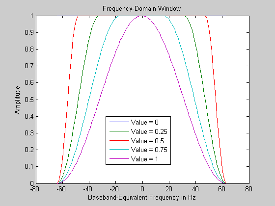
Fraction of modeling bandwidth , specified as a scalar. Fraction of modeling bandwidth over which to taper the edges of the transfer function of the system when creating the baseband-equivalent model. This parameter defines the ratio of the bandwidth of sections that are tapered using a Tukey, or cosine-tapered, window to the bandwidth of the constant, or untapered, sections.

A value less than or equal to 0 tells the Input Port block to use a rectangular (rectwin (Signal Processing Toolbox)) window. A value greater than or equal to 1 tells the Input Port block to use a hann window.

Number of time samples by which to delay the impulse response of the baseband-equivalent model, specified as a scalar. Setting Modeling delay (samples) ensure that the baseband-equivalent model has a causal response.

See Create Complex Baseband-Equivalent Model for information on how the Input Port block applies this delay to ensure a causal response.

Center of the modeling frequencies, specified as a scalar. See the Output Port block reference page for information about calculating the modeling frequencies.

Time interval between consecutive samples of the input signal, specified as a scalar.

Note

The Input Port block does not automatically inherit a sample time from its input signal. The specified Sample time (s) value must match the sample time of the input signal.

Specifying the type of processing mode the block performs as one of the following:

  • Elements as channels (sample based): Set the Input processing to Elements as channels (sample based), if your block needs to process based on sample-based model. In sample-based processing, blocks process signals one sample at a time. Each element of the input signal represents one sample in a distinct channel.

  • Columns as channels (frame based): Set the Input processing to Columns as channels (frame based), if your block needs to process based on frame-based model. In frame-based processing, blocks process data one frame at a time. Each frame of data contains sequential samples from an independent channel. Each channel is represented by a column of the input signal.

Add noise data to block, specified as a on or off. If you select this parameter, noise data in the RF physical blocks that are bracketed by the Input Port block and Output Port block is taken into consideration. If you do not select this parameter, noise data is ignored.

Initial seed for random number generator block to generate noise, specified as a nonnegative integer to generate noise. This parameter becomes visible if you select the Add noise parameter. If you specify the initial seed parameter with a variable, the initial seed changes each successive time you run a model.

Dependencies

To enable this parameter, select Add noise parameter.

More About

expand all

Version History

Introduced before R2006a
See Also