Mixer
Model RF and IQ modulator and RF and IQ demodulator with impairments and noise

Libraries:
RF Blockset /
Idealized Baseband
Description
The Mixer block models four complex baseband mixers and with impairments and noise. The four mixer types that the block models are Modulator, Demodulator, IQ Modulator, and IQ Demodulator. Impairments include IQ gain and phase mismatch where appropriate, while noise includes both system and LO phase noise.
Note
Idealized Baseband library blocks assume input and output ports are matched. For more information on port signal power, see Power Ports and Signal Power Measurement in RF Blockset.
Idealized Baseband library blocks are single carrier with assumed carrier frequency value. Therefore the Ideal Baseband Mixer block can produce only a single sideband output.
Mixer block mask icons are dynamic and indicate the current set of applied noise parameters. For more information, see Mixer Block Icons.
Examples
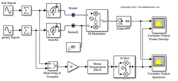
Modulate Quadrature Baseband Signals Using IQ Modulators
Modulate quadrature baseband signals using two different RF Blockset™ blocks. You can use either an idealized baseband Mixer block or a circuit envelope IQ Modulator block in your model to modulate quadrature baseband signals to the RF level. Observe the impairments in the modulated output signal due to gain imbalance, third-order intercepts (OIP3) and system noise in the complex output power density and output power spectrum analyzers.
Ports
Input
Output
Parameters
Algorithms
Architectural models for the Mixer block are shown here. Mixer and phase noise for all cases are included here.
Modulator and demodulator architectures includes system noise, phase noise, and nonlinear polynomials to translates the carrier. A random number generator is used as an input to generate phase noise.

The output of the ideal modulator and demodulator circuit with nonlinearities, Yout, is given by this equation.
Where,
The nonlinear polynomial coefficients, c1 and c3 , are provided in Nonlinearities in Idealized Baseband Mixer Block.
The IQ modulator primary consists of two mixers, fI() and fQ(). The Mixers convert baseband signals to RF signals and are commonly used in direct conversion architectures. The fI() and fQ(), are responsible for introducing gain, gain imbalance, phase imbalance, and nonlinearities into the IQ demodulator.

The output of IQ Modulator, Yout, is given as
where,
The nonlinear polynomial coefficient c3 are provided in Nonlinearities in Idealized Baseband Mixer Block. The modulators linear gains are c1 and c1Q are provided in this equation.
where,
The architecture of an IQ demodulator is given below. The in-phase, Iout, and quadrature component, Qout, of the modulated signal are the output of the fI() and fQ(), respectively. The mixers, fI() and fQ() are responsible for introducing gain, gain imbalance, phase imbalance, and nonlineatites into the IQ demodulator.

The output of the IQ Demodulator, Yout, is given as
where,
The nonlinear polynomial coefficient c3 are provided in Nonlinearities in Idealized Baseband Mixer Block. The modulators linear gains c1 and c1Q are provided in this equation.
where,
This table shows you how the icons on this block will vary based on how you set the Parameters on the block.
| Mixer Type | Include Mixer Noise | Include Phase Noise: off | Include Phase Noise: on |
|---|---|---|---|
Modulator | off |
|
|
on |
|
| |
| Demodulator | off |
|
|
on |
|
| |
| IQ Modulator | off |
|
|
on |
|
| |
| IQ Demodulator | off |
|
|
on |
|
|


Note
After you set the block parameters you must click the Apply button to see the icon change.
References
[1] Razavi, Behzad. “Basic Concepts “ in RF Microelectronics, 2nd edition, Prentice Hall, 2012.
[2] Kundert, Ken.“ Accurate and Rapid Measurement of IP2 and IP3,“ The Designer Guide Community, May 22, 2002.
[3] Kasdin, N.J. “Discrete Simulation of Colored Noise and Stochastic Processes and 1/f α Power Law Noise Generation.” Proceedings of the IEEE 83, no. 5 (May 1995): 802–27. https://doi.org/10.1109/5.381848.
Extended Capabilities
Version History
Introduced before R2006aStarting in this release, the extrapolated low-frequency phase noise below the first frequency point that specifies the 1/f^3 in the Mixer block is now 30 dB/decade instead of 3 dB/decade.
When you open a model created before R2023a containing the Mixer block and click the Plot Phase Characteristics button, the software scales the phase noise level in dBc/Hz on the y-axis in a phase noise magnitude response plot.
For example, open the Mixer block and select Include Phase Noise.
Set the Number of signal samples to 2^10 and click
the Apply button. Click the Plot Phase
Characteristics button to plot the phase noise magnitude response and observe
that the first frequency point that specifies the 1/f^3 in the Mixer block is
scaled to 30 dB/decade.
