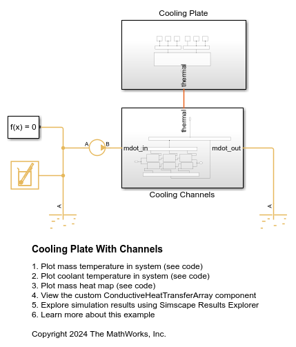
Cooling Plate with Channels
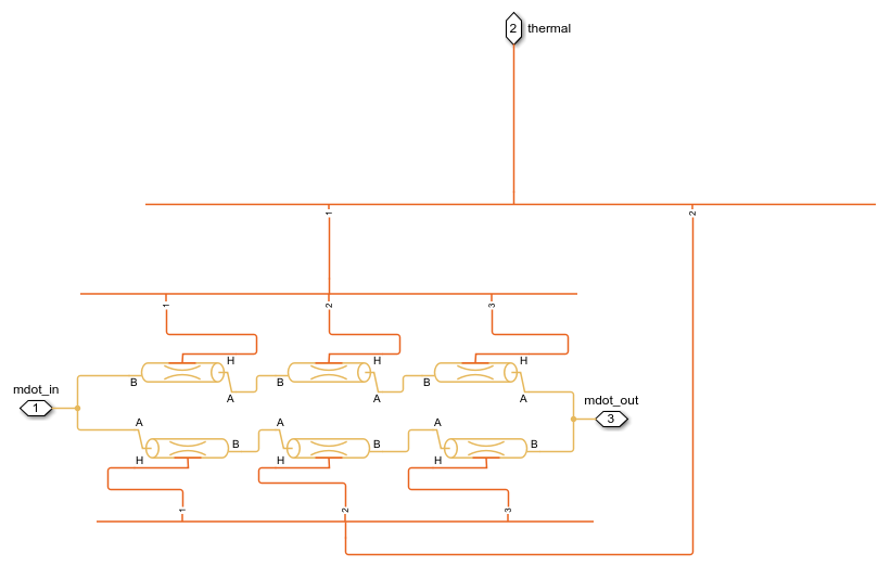
This example shows a discretized cooling plate with cooling channels, divided into six segments: three on the top and three on the bottom. Each cooling plate segment is modeled as a thermal mass, while cooling channels are modeled using the Pipe (TL). The ConductiveHeatTransferArray, a custom component, models thermal conduction between the cooling plate segments.

The model uses Array Connection blocks, both in Scalar Elements and Sized Elements mode, to group signals into Arrays of Nodes. This facilitates interaction with the Simscape™ language and helps to clean up the block diagram, reducing clutter and enhancing readability.
The model defines the material properties, initial thermal mass temperatures, and geometry to represent the plate, and also sets up pipe geometry parameters, such as length, diameter, and hydraulic diameter.
Model
Cooling Channels Subsystem
Cooling Plate Subsystem

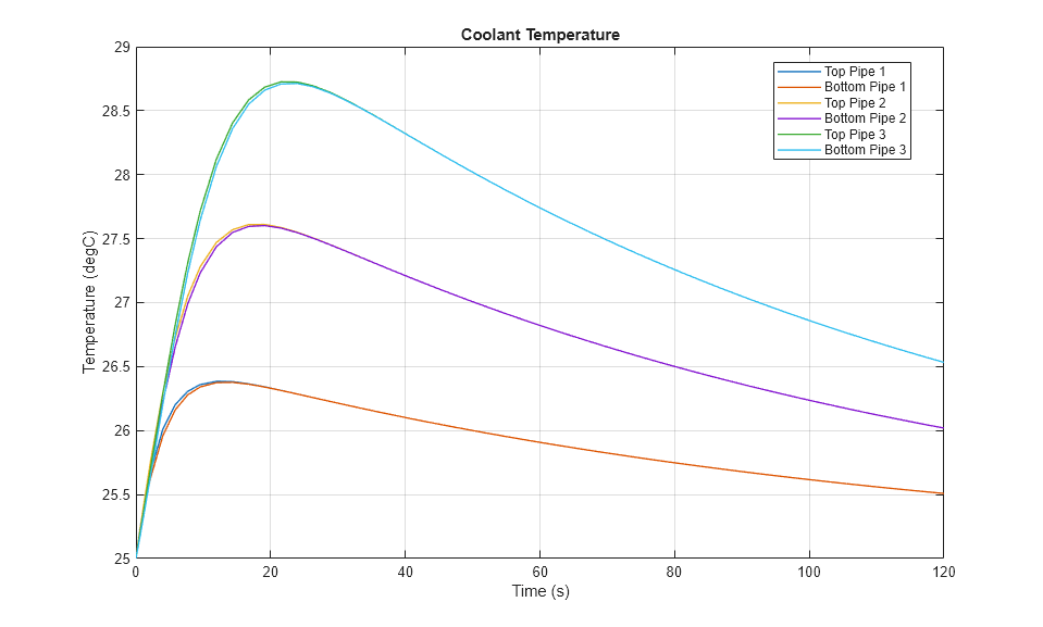
Simulation Results from Simscape Logging
This plot shows the temperature of the coolant at different locations in the system over time. Each curve corresponds to a segment of the cooling channels.
This plot shows a heat map of the temperature of the cooling plate over time. Each heat map cell corresponds to a thermal mass in the system. You can adjust the simulation time using the slider at the bottom of the figure.

This plot shows the temperature of the cooling plate masses at different locations in the plate over time. Each curve corresponds to a segment of the cooling plate.
