Spring-Loaded Clutch
This example models the engagement response of a spring-loaded clutch. The plate contains four helical springs arranged in a circular pattern. The example describes these key parts of the model:
Connecting Rotational Spring (AB) blocks in parallel.
Configuring Rotational Spacer (AB) blocks to offset angles between springs and assigning high-priority targets to avoid over-constraint.
Using Rotational Motion Sensor (AB) blocks and Simscape Probe blocks to measure angles of components.
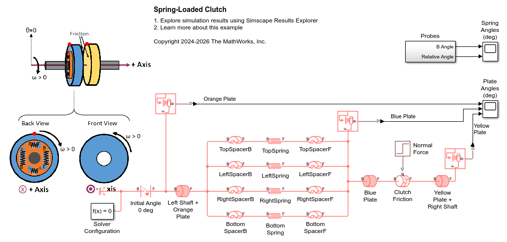
Model
This model consists of:
An Inertia (AB) block models a left shaft rigidly attached to an orange plate.
The orange plate connects to a blue friction plate via four rotational spacer-spring-spacer branches arranged in parallel. Each branch represents a different helical spring between the plates with a different angle offset from the orange plate.
A Rotational Friction (AB) block, labeled Clutch Friction, models friction between the blue and yellow plates.
The yellow friction plate is rigidly attached to a right shaft, modeled by a single Inertia (AB) block.
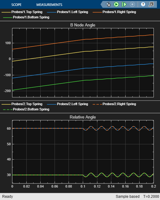
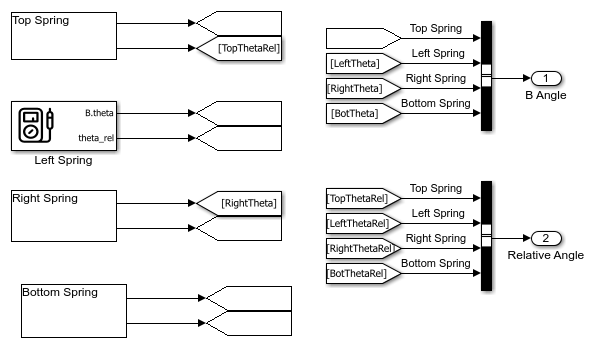
Probes Subsystem
Simscape Probe blocks log the B port angle and the relative angle between ports of each spring. The B port of each spring corresponds to the end of that spring that is attached to the orange plate.
Initial Conditions
As shown by the theta=0 direction in the physical view, 0 deg in the world frame is defined as upward. The red dots in the physical view represent tracking points for the plate angles. All plates start with angles of 0 deg.
The initial states of the four springs at rest are described in this table (units of degrees):
     Spring     RelativeAngle    AngleOfPortB    AngleOfPortF
    ________    _____________    ____________    ____________

    "Top"            30               -15              15
    "Left"           60              -120             -60
    "Right"          60                60             120
    "Bottom"         30              -195            -165
Left Shaft + Orange Plate and Blue Plate start at Angular velocities of 100 rpm.
Yellow Plate + Right Shaft start at an Angular Velocity of 0 rpm.
All four springs start with zero Torque.
Each spring's Relative angle matches the values shown in the table.
The top branch sets the angle between the orange plate and blue plate to 0 degrees by assigning high priority to SpacerTopB and SpacerTopF Relative angles.
For the other branches (left, right, and bottom), only the first spacer in each branch has a high-priority target for Relative angle. The Relative angle of the second spacers are left with "None" priority so the solver can compute consistent angles without over-constraining the system.
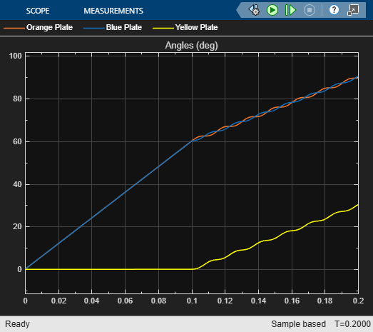
Simulation Results from Scopes
At the start of the simulation, all plates are at 0 degrees. The orange and blue plates rotate at 100 rpm, while the yellow plate remains stationary. At 0.1 seconds, the clutch engages: the yellow plate begins to accelerate, and the orange and blue plates decelerate. All plates exhibit some oscillatory behavior during this process.
The initial angles of each spring's B port match the values shown in the table. Throughout the simulation, the angles of the spring B ports and their relative angles maintain constant offsets from each other. The relative angles of the springs oscillate as the orange and blue plates oscillate.