Using Variant Connectors to Implement Variations in Physical Networks
A variant design is a method for managing design alternatives in one artifact. Variant design with the Variant Connector block is expressed as conditional manifestation of components within a physical network. Each design choice is incorporated into the network as a variant choice. Such models have a fixed common structure and a finite set of variable components that are activated or deactivated depending on the variant control you select. For more information, see Introduction to Variant Controls.
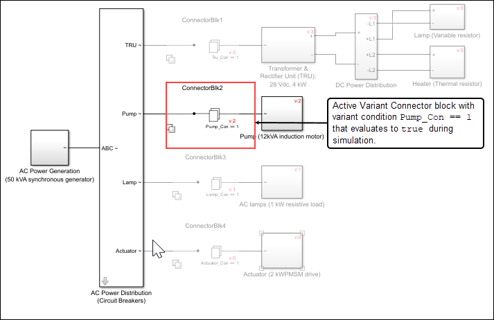
Consider an in-flight fuel imbalance scenario, where the quantity of fuel between the fuel tanks in the left and right wings of an aircraft is unequal. To maintain airplane lateral balance, you must pump the fuel so that the load between the left- and right-wing tanks is symmetrical. In this scenario, the only component required is the pump. All other power distributor components, such as Transformer Rectifier Units (TRUs), AC lamps, and actuators, can be excluded from simulation as they are not required to balance the fuel in the wings. You can set the variant control to activate only the pump.
The code that you generate for the Variant Connector block contains only the active components of a system. Inactive components do not participate in code generation.
Limitations
The Variant Connector block does not propagate the variant condition across the boundary between the Simscape™ physical network and the Simulink® blocks connected to it.
Propagated variant conditions from variant blocks can be set on Simscape only for the
update diagramvariant activation time.