Model-Based Design with Simulink
Modeling is a way to create a virtual representation of a real-world system. You can simulate this virtual representation under a wide range of conditions to see how it behaves.
Modeling and simulation are valuable for testing conditions that are difficult to reproduce with hardware prototypes alone. This is especially true in the early phase of the design process when hardware is not yet available. Iterating between modeling and simulation can improve the quality of the system design early, by reducing the number of errors found later in the design process.
You can automatically generate code from a model and, when software and hardware implementation requirements are included, create test benches for system verification. Code generation saves time and prevents the introduction of manually coded errors.
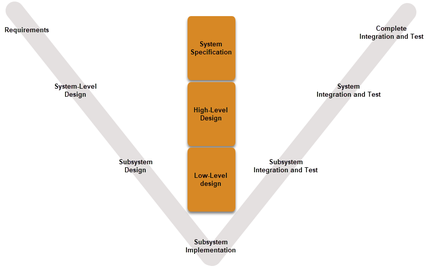
In Model-Based Design, a system model is at the center of the workflow. Model-Based Design enables fast and cost-effective development of dynamic systems, including control systems, signal processing systems, and communications systems.
Model-Based Design allows you to:
Use a common design environment across project teams
Link designs directly to requirements
Identify and correct errors continuously by integrating testing with design
Refine algorithms through multidomain simulation
Automatically generate embedded software code and documentation
Develop and reuse test suites

Example Model-Based Design Workflow in Simulink
To get started with a Model-Based Design task, consider this workflow.

The workflow in this tutorial focuses on fundamental Simulink® tasks as they relate to Model-Based Design.
System Definition and Layout — Identify modeling goals, determine components, model system layout.
Model and Validate a System — Model and test components, integrate components, test system.
Design a System in Simulink — Design and test new components.
The first two tasks in this workflow model an existing system and establish the context for designing a component. The next step in this workflow would be to implement the new component. You can use rapid prototyping and embedded code generation products, such as Simulink Real-Time™ and Embedded Coder®, to generate code and use the design with a real, physical system.
See Also
Topics
- System Definition and Layout
- Model and Validate a System
- Design a System in Simulink
- Organize Large Modeling Projects Using Referenced Projects