Convert Subsystems to Referenced Models
Model reference offers benefits for modeling large, complex systems and for team-based development. Many large models use a combination of subsystems and referenced models. To decide whether to convert a subsystem to a referenced model, see Explore Types of Simulink Components.
A subsystem you convert must have atomic behavior that functionally groups the blocks. The blocks in the subsystem must execute consecutively and behave like a single block, or atomic unit, when the parent model executes. For more information, see Specify Whether Subsystem Is Atomic. The atomic behavior can cause artificial algebraic loops. For more information, see Algebraic Loop Concepts.
Prepare Subsystem for Conversion
Preparing a subsystem for conversion can eliminate or reduce the number of issues identified during conversion. Addressing these issues before conversion can be more efficient than switching repeatedly between the diagnostic messages and the Simulink® Editor.
The software can automatically fix some issues during conversion. To respect the original design intent, the automatic fixes might apply less clean solutions than you can apply manually. For example, the software might place the Model block in a subsystem, use extra blocks, or append a parenthetical to signal names.
To prepare the subsystem for conversion:
To ensure the subsystem has atomic behavior, select the Subsystem block. In the Simulink Toolstrip, on the Subsystem Block tab, select Make Atomic.
To minimize artificial algebraic loops that the atomic behavior might create, select the Subsystem block. In the Property Inspector, select Minimize artificial algebraic loop occurrences.
Note
To open the Property Inspector, in the Simulink Toolstrip, on the Modeling tab, in the Design gallery, select Property Inspector. Alternatively, press Ctrl+Shift+I.
To avoid implicit signal resolution to
Simulink.Signalobjects, configure a parent model setting. Set the Signal resolution configuration parameter toExplicit only(default) orNone.Note
To open the Configuration Parameters dialog box, in the Simulink Editor, on the Modeling tab, perform one of these actions:
If the parent model is a top model, click Model Settings.
If the parent model is a referenced model, click the Model Settings button arrow. Then, in the Referenced Model section, click Model Settings.
Fix the conversion issues in this table, if applicable.
Conversion Issue Manual Fix A Function-Call Generator block provides input to a subsystem that is not an export-function subsystem.
Move the Function-Call Generator block into the subsystem.
A wide (nonscalar) function-call signal is input to the function-call input port of a subsystem.
Trigger the subsystem with a scalar function-call signal instead.
A function-call signal is an output of the subsystem.
Change the function-call output to a data trigger.
A Merge block combines the signals from the subsystem input ports.
Configure the subsystem to avoid the Merge block.
Bus elements have duplicate names.
Assign unique names to the elements.
A Goto block passes input to a From block that is outside the subsystem.
Replace each problematic Goto block with an Outport block. Then, connect the new subsystem output ports to blocks in the parent system.
A From block receives input from a Goto block that is outside the subsystem.
Replace each problematic From block with an Inport block. When the From blocks have the same tag, duplicate the Inport block that replaces the first of the From blocks instead of adding unique Inport blocks for each From block. For more information, see Create Duplicate Inport Blocks. Then, connect the new subsystem input ports to blocks in the parent system.
The subsystem uses global tunable parameters specified in the dialog box that opens when you click the Configure button next to the Default parameter behavior (Simulink Coder) configuration parameter.
To create a
Simulink.Parameterobject for each tunable parameter, usetunablevars2parameterobjects. EachSimulink.Parameterobject must have a storage class other thanAuto. For more information, see Configure Instance-Specific Values for Block Parameters in a Referenced Model and Tunable Parameters.A Parameter Writer block writes to:
A block outside the subsystem
A base workspace variable used outside the subsystem
A model workspace variable
Move the Parameter Writer block outside the subsystem.
To support conversion:
Parameter Writer blocks must be on the same side of the subsystem boundary as their parameter owner blocks.
Parameter Writer blocks that write to model workspace variables must be outside the subsystem. The conversion introduces a new model workspace for the new model.
The sample time differs between a block that represents an input port and the block that drives the input port.
Change one of the two sample times to match the other or insert a Rate Transition block.
The sample time at an input port is constant.
Move each source block with a constant sample time into the subsystem. For example, move Constant blocks into the subsystem.
Compile the model and resolve errors.
For the conversion to succeed, the model that contains the subsystem must compile successfully.
Convert Subsystems to Referenced Models
To convert a subsystem to a referenced model:
To make the conversion process faster, close Scope block windows.
Select the Subsystem block you want to convert.
In the Simulink Toolstrip, on the Subsystem Block tab, click Convert > Referenced Model.
To automatically fix some conversion issues, in the Model Reference Conversion Advisor, select Fix errors automatically (if possible). You do not control the automatic fixes.
To replace the Subsystem block with a Model block that references the new model, check that Replace the content of a subsystem with a Model block is selected.
To compare top-model simulation results before and after conversion:
Enable signal logging for output signals of interest.
Select Check simulation results after conversion and Replace the content of a subsystem with a Model block.
Set the Stop time, Absolute tolerance, and Relative tolerance.
Set the Model block simulation mode option in the advisor to the same simulation mode as the original model.
Optionally, configure additional conversion parameters. For more information, see Model Reference Conversion Advisor.
Click Convert.
Address the identified issues.
Alternatively, in the MATLAB® Command Window, use the Simulink.SubSystem.convertToModelReference function. You can convert
multiple Subsystem blocks using one
Simulink.SubSystem.convertToModelReference command. However, you
cannot convert a parent subsystem and a child of that subsystem at the same time.
Conversion Results
After the conversion checks pass, the software:
Creates a new model from the subsystem.
Creates the
Simulink.Busobjects,Simulink.Signalobjects, and tunable parameters that the new model requires.By default, replaces the Subsystem block with a Model block that references the new model.
Inserts the Model block in a Subsystem block if the automatic fixes added ports to the Model block interface.
Creates an HTML conversion summary report in the
slprjfolder. This report summarizes the results of the conversion process, including the results of the fixes that the advisor performed. This report also describes the elements that it copies.Optionally checks the consistency of simulation results before and after conversion.
The software copies these elements from the parent model to the new model.
Configuration set — If the parent model references a freestanding configuration set, then the new model typically references the same configuration set. Otherwise, the advisor copies the configuration set of the parent model to the new model. To support using the new model as a referenced model, the conversion overrides incompatible parameter values in a referenced configuration set (since R2026a) or changes incompatible parameter values in a copied configuration set.
For example, suppose the parent model has Signal resolution set to
Explicit and implicitorExplicit and warn implicit. To avoid implicit signal resolution toSimulink.Signalobjects in the new model, the new model sets Signal resolution toExplicit only. (since R2025a)Variables — The advisor copies only the model workspace variables that the subsystem used in the parent model to the model workspace of the new model. If the parent model uses a data dictionary, then the new model uses the same data dictionary.
Requirements links — The advisor copies requirements links created with Requirements Toolbox™ software to the Model block from the original Subsystem block.
When the conversion checks fail, you receive the option to copy the subsystem block diagram to a new model. The new model uses the configuration set from the original parent model. If you want to force the conversion and resolve errors manually after the conversion, use this option. (since R2026a)
Alternatively, use the Simulink.SubSystem.convertToModelReference function with
Force set to true.
Compare Simulation Results Before and After Conversion
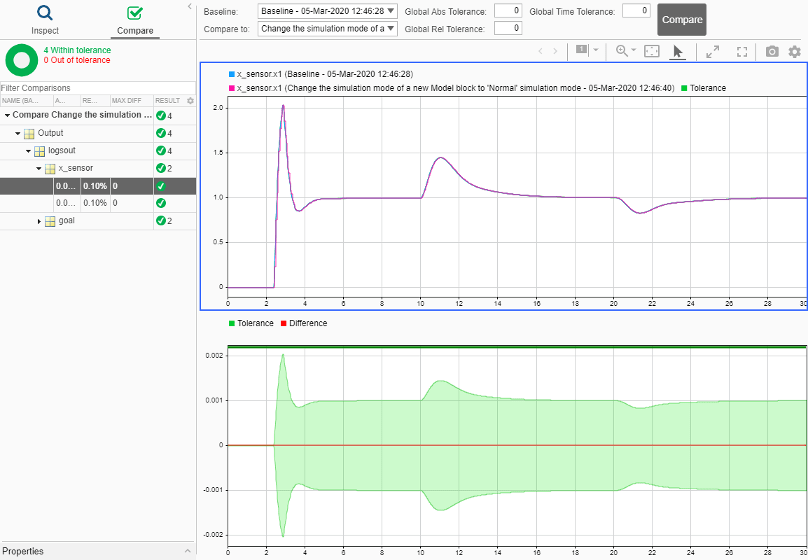
After you successfully complete conversion, use the Click here to view the comparison results link. The results display in the Simulation Data Inspector. A green check mark indicates that simulation results are within tolerance between the baseline model and the model with the new referenced model.
For more information, see Compare Simulation Data.
Revert Conversion
If you are not satisfied with the conversion results, you can restore the model to its initial state. Use one of these approaches:
At any point during the conversion, select File > Load Restore Point.
After you successfully run the Complete conversion check, use the Click here to restore the original model link.
Integrate Referenced Model into Parent Model
After you complete the conversion, update the model as necessary to meet your modeling requirements. For example, you can manually replace a Subsystem block with a Model block that references the new model.
If you want to simulate the model with external data, check that the root Inport blocks in the new model have the appropriate Interpolate data parameter setting. For more information, see Interpolate data.