Analyze Variant Configurations in Models Containing Variant Blocks
Note
This functionality requires Variant Manager for Simulink®.
A model might contain several variant blocks or variant parameters, each with many variant choices. A variant configuration is used to represent a combination of such variant choices across the model hierarchy. For example, in a system with a plant and a controller, a linear controller with an internal plant with no noise and a nonlinear controller with an external low fidelity plant represent two different configurations of the system.
You can use Variant Manager to create and manage variant configurations for a model. Variant Manager defines a variant configuration as a set of variant control variables and their values that can activate a specific variation in the model hierarchy. For more information on variant configurations, see Variant Configurations. For an overview of Variant Manager, see Variant Manager for Simulink.
Analyze Variant Configurations Using Variant Analyzer
Use Variant Analyzer to:
Compare different variant configurations for a model to understand the model elements used in each.
Check if all variant choices have been activated at least once and whether the model is covered completely for simulation and code generation.
Verify if the active, implemented model is different between different variant configurations.
Find dependent model artifacts such as referenced models and libraries used by a particular variant configuration.
You can analyze the named variant configurations created for the model or perform an analysis after setting values for the variant control variables. The report generated by the tool displays:
Variant configurations analyzed
A model hierarchy with all the blocks
Variant activeness of each block in each variant configuration
Propagated variant conditions on a block for each variant configuration
The analysis results help you to determine which blocks are used in different variant configurations. The unused blocks are highlighted in red, which represents untested and uncovered parts of the model. The heatmap view helps you determine the similarities and differences in the active, implemented model between different variant configurations. This information can be used to refine the variant configurations and to update the model to provide full simulation coverage across all variant configurations.
Run Variant Analyzer
Open the variant model that must be analyzed. Here, open the
slexVariantConfigurationAnalysismodel using the following command.openExample('simulink_variants/AnalyzeVariantConfigurationsInModelRefPageExample'); open_system('slexVariantConfigurationAnalysis');
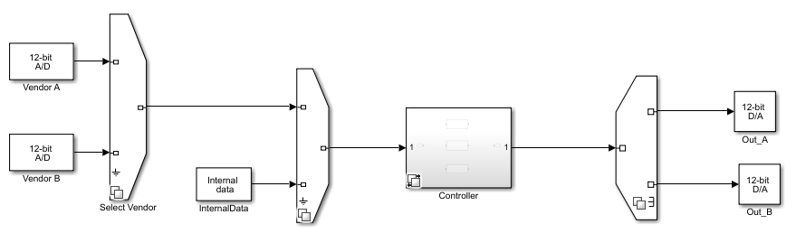
This model contains multiple vendor choices for the sensors and different controller implementations based on the sensor input. The choice of vendor sensors is modeled with Variant Source and Variant Sink blocks. The different controller choices is modeled using Variant Subsystem block.
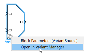
Open Variant Manager. On the Modeling tab, open the Design section and click Variant Manager. Alternatively, right-click the variant badge on any variant block and select Open in Variant Manager.
The Variant Manager opens and displays the predefined configurations. To open Variant Analyzer, in the Variant Manager toolstrip, in the Apps section, click Variant Analyzer.
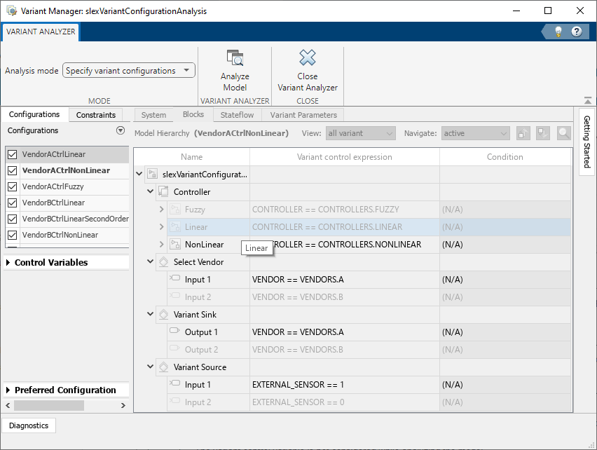
For Analysis mode, choose whether to analyze the predefined named configurations for the model or if you need to specify values for the variant control variables.
Specify variant configurations — Select from the list of named variant configurations in the Configurations tab.
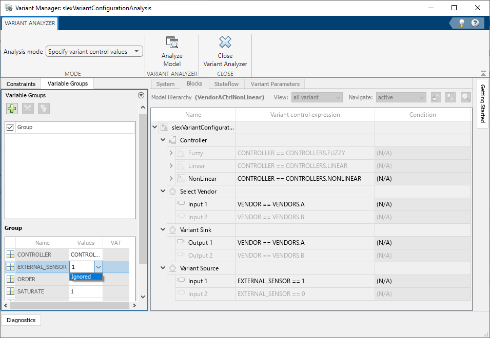
Specify variant control values — Analyze the model by specifying values for the variant control variables. You can create multiple variable groups that correspond to different variant configurations to be analyzed. In each variable group, you must specify the variant control variables and the values to be considered for each variable.
To add a new variable group, click the Add variable group button
 in the Variable Groups table
and set the values for variant control variables. You can either specify a variant
control value or select
in the Variable Groups table
and set the values for variant control variables. You can either specify a variant
control value or select Ignoredfrom the Values list.Variant control value as a vector — Analyze for all combinations of the specified values. For example, if you specify values
V = 1andW = [1,2], then the model is analyzed for the configurations{V == 1, W == 1}and{V == 1, W == 2}.Ignored— The variant control variable is not considered while analyzing the model.
Click Analyze Model. The variant analysis report opens in a new window.
Click Close Variant Analyzer to return to the Manage tab in Variant Manager.
Explore Variant Analysis Report
The variant analysis report displays a tree-table view of the model hierarchy and all of the analyzed variant configurations.
This image shows the analysis report for four named variant configurations.
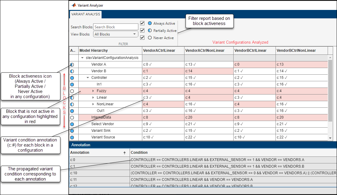
Icons and Formatting
This table explains the icons and formatting used in the report.
| Formatting | Meaning |
|---|---|
Rows and Columns | Each row in the table corresponds to a block in the model. Each column represents a variant configuration. |
Check mark | The |
Background color | An entire row including the block name appears with a red background color if it is not active in any of the variant configurations. Such a block indicates an untested path in the model. A table field with red background color indicates that a particular block is not active in a specific configuration. For example, in this model,
the |
Block activeness icons | The |
Variant condition annotations ( | The annotations in the table fields represent a variant condition that the block receives for a particular configuration. The propagated variant condition on a block changes according to the active variant configuration. You can refer the table in the
Annotation pane for mapping between the annotations
( |
Filter the Report
Filter the report based on your desired type of filter.
| Desired Filter | Filtering Method |
|---|---|
Name of block | Enter the block name in the Search Blocks box and press Enter. |
Type of block | Select an option from the View Blocks list:
|
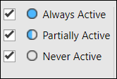
Block activeness |
|
Example Variant Analysis Reports
Consider this report for a model with several unused blocks. The Never Active option is selected to view the unused blocks.
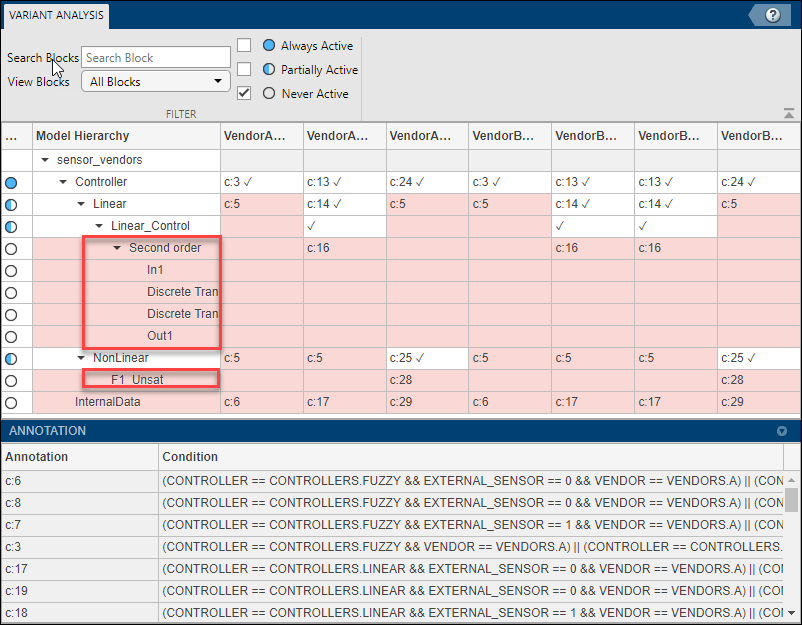
The blocks in the Second order controller inside the
Linear_Control and F1_Unsat filter are unused. To
make these unused blocks part of the active model in at least one of the variant
configurations, modify the model or update the variant configurations.
This image shows the report for a model with two identical variant configurations. The Partially Active option is selected to get this result.
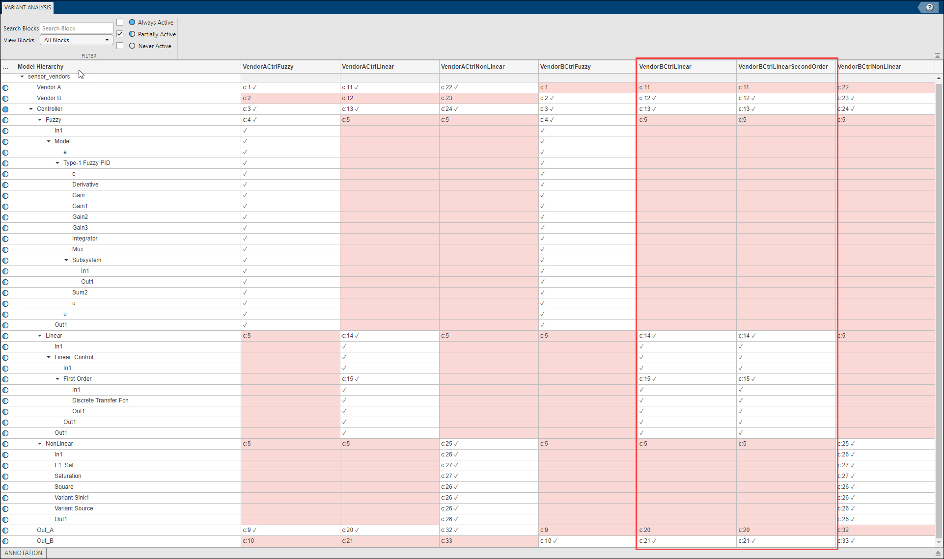
The variant configurations VendorBCtrlLinear and
VendorBCtrlSecondOrder have no differences between them. The
resulting active model for both these configurations will be the same. To resolve this
result, update the variant configurations or update the model appropriately.
Analyze Variant Configurations Programmatically
Use an instance of the Simulink.VariantConfigurationAnalysis class to analyze variant configurations
programmatically.
Limitations
Variant Analyzer does not support models that contain variant blocks that use variant control variables defined in the mask or model workspace.
See Also
Simulink.VariantConfigurationData | Simulink.VariantConfigurationAnalysis