Generate Test Cases for a Model
In Simulink® Design Verifier™, a test case is a set of input values and corresponding expected outputs used to verify that a model behaves as intended under specified conditions. With Simulink Design Verifier, you can generate test cases for model coverage and custom objectives. You can also measure coverage of existing requirements-based test cases and extend these test cases to increase coverage or achieve full coverage.
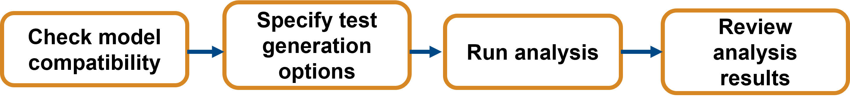
Before you start an analysis, run a compatibility check on your model. Simulink Design Verifier analyzes the model only if it is compatible with the analysis. After the compatibility check, specify test case generation settings on the model and run the analysis. Once the test generation analysis is complete, review the results.
There are several ways to review the analysis results:
Review the analysis results at a glance by highlighting the results on the model.
Create a test harness model to simulate the test cases or debug counterexamples.
Generate a model coverage report.
View generated tests in the Simulation Data Inspector.
Generate an HTML or PDF report that contains detailed information about the analysis results.
Example Model
This tutorial uses a simplified cruise control model
sldvexCruiseControl that adjusts the engine throttle to
maintain specified speed. You generate test cases that satisfy condition and
decision model coverage objectives and then simulate these test cases to generate
the model coverage report.

This cruise control model sldvexCruiseControl meets these requirements:
The control system is activated when the
engageand theenablesignals aretrue. This condition is defined by the AND block.When the system is activated, the Switch block passes
set speedto the PI controller. The PI controller calculatesthrottleby integrating the error term defined by the differenceset speed - current speed.throttlecontinues to increase or decrease untilset speedis greater thancurrent speedor less thancurrent speed, respectively.When the system is not activated, the Discrete-Time Integrator block resets. The error term is zero, which means the
throttleis in reset position.
When you perform test generation analysis, Simulink Design Verifier generates test cases for the model coverage objectives associated with each model item in the model. The table lists the condition and decision coverage objectives for the associated Model blocks.
| Block | Model Coverage Objective | Generated Test Case Description |
|---|---|---|
| AND | Condition | Each input value is set to true or false independently. |
| NOT | Condition | Input is set to true or false independently. |
| Switch | Decision | Test case demonstrates that the Switch passes both the input signals to output. |
| Discrete-Time Integrator | Decision |
|
In this tutorial, you perform test generation analysis on the
sldvexCruiseControl model. The analysis generate test cases
that satisfy condition and decision model coverage objectives.
You will learn how to:
Configure model settings for Simulink Design Verifier analysis.
Check model compatibility for test generation analysis.
Configure model to generate tests and perform the analysis.
View test generation analysis results.
Create harness model and generate coverage report.
To start the tutorial, see Prepare Model for Test Generation Analysis.