Handle Model Complexities with Automatic Stubbing
Stubbing in Simulink® Design Verifier™ is the process of replacing certain parts of a model with simpler representations, or stubs, to enable analysis. Automatic stubbing enables analysis of models that contain complex elements. Simulink Design Verifier stubs elements for the duration of the analysis or only during specific phases in the analysis. For example, the Float Extract Bits block is stubbed for the entire analysis, whereas trigonometric function blocks may be stubbed only during certain phases, such as when Simulink Design Verifier analyzes model to identify dead logic. Simulink Design Verifier analysis assumes that the output of a stubbed block can take any value within its full possible range when evaluating downstream blocks.
The analysis results obtained with automatic stubbing may be affected by the use of stubs. Stubbing can prevent the analysis from fully exploring the behavior of block, which may result in some objectives being undecided or not covered. The objectives that are impacted due to stubbing are indicated by the Undecided due to Stubbing status. For more information, see Objectives Status Chapter.
How Automatic Stubbing Works
Automatic stubbing may restrict analysis for certain parts of the model, Simulink Design Verifier continues to analyze the remaining components. The table summarizes the effects of stubbing on the analysis results.
| Analysis | Effects of Stubbing on Results |
|---|---|
Design error detection |
|
Test case generation |
|
Property proving |
|
Review Automatic Stubbing Analysis Results
Simulink Design Verifier stubs blocks and provides analysis results based on the abstracted behavior of those blocks.
When analysis completes without any undecided objectives, the information about stubbed blocks does not appear in the Diagnostic Viewer, analysis report, or
sldvData. For an example, see Analysis Completes Without Undecided Objectives.When analysis completes with undecided objectives due to stubbing, the Diagnostic Viewer,
sldvData, and analysis report display all stubbed blocks in the model. For an example, see Analysis Completes With Undecided due to Stubbing Objective Status.
Analysis Completes Without Undecided Objectives
The Simulink Design Verifier analysis determines the status of all objectives, even when stubbing is applied. In this case, you can view the results as usual, and the software does not display a notification indicating that stubbing occurred.
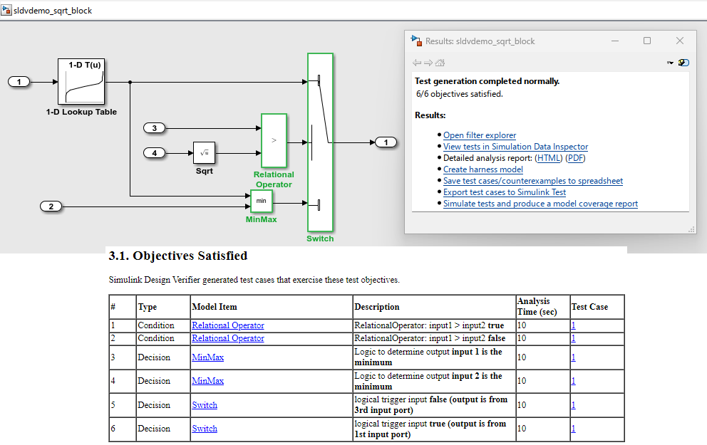
Consider this model with a Switch block whose output depends on a Sqrt block. The output for each switch position is determined by a 1-D Lookup Table block. When you run test generation analysis, Simulink Design Verifier stubs the Sqrt block. The stubbed behavior does not impact other blocks, the analysis produces complete results, and all six objectives are satisfied. The results are complete and the analysis report does not show any details about the stubbed Sqrt block.
Analysis Completes With Undecided due to Stubbing Objective Status
When stubbing impacts the objective status, Simulink Design Verifier analysis report indicates that the block is not supported or that objective status is Undecided due to Stubbing. The Diagnostic Viewer displays warnings about all stubbed blocks, regardless of whether Simulink Design Verifier can abstract their behavior.
Consider the model that contains a Math Function block that is stubbed during analysis. If you run design error detection analysis, the Diagnostic Viewer shows a warning that the analysis is impacted by the Math Function block. This is because some conditions inside the blocks are triggered based on the inputs to the block. When a block is stubbed during analysis, Simulink Design Verifier may be able to reach certain conditions through the available inputs, while other conditions may not be reachable.
The Results dialog box indicates that one out of two objectives has an Undecided due to Stubbing status. The analysis report contains a table of unsupported blocks encountered during analysis.

Achieve Complete Results
You can define custom block replacements to give a more precise definition of the unsupported blocks. For more information, follow the steps in Template for Block Replacement Rules.
For additional guidance, see the workarounds in Resolve Undecided Objective Statuses Resulting from Model Complexity for stubbing.
Note
Automatic stubbing does not affect the code generation process or the resulting generated code. The generated code reflects the interpretation of the model.