Model a Four-Bar Mechanism
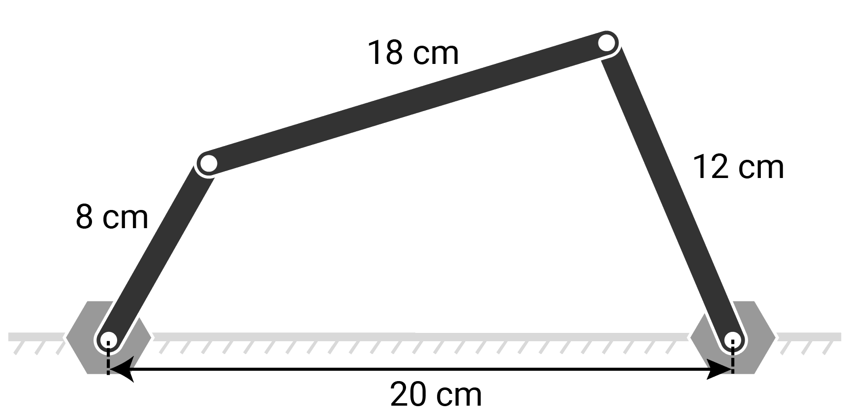
This example shows how to model a four-bar mechanism, specifically a crank-rocker mechanism with links measuring 8 cm, 12 cm, 18 cm, and 20 cm in length.
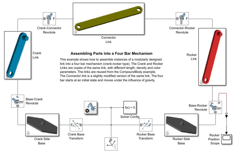
In this example, you reuse a pre-constructed link model to assemble the four-bar mechanism. The crank and rocker links are copies of the same link, but with different lengths, densities and color parameters. The connector link is a slightly modified version of the same link. Two rigidly connected pivots represent the ground link, which is rigidly connected to the world frame. The image shows the block diagram of the four-bar model.
Use four Revolute Joint blocks to assemble the links into the four-bar mechanism. To specify the initial state of the four-bar mechanism, set the position targets of the Base-Crank and Crank-Connector revolute joints to 150 degrees and -45 degrees, respectively. To drive the four-bar mechanism, set a constant velocity of -360 degrees per second for the Base-Crank revolute joint. The crank link rotates clockwise. For another example of four-bar system modeling, see Model a Closed-Loop Kinematic Chain.